Electrical schemes for electric guitars
This page is intended as a basic introduction to electric guitar circuits based on passive components. For anything more advanced or a more in-depth explanation, you should seek out more elaborate documentation or a course in electronics.
Most passive guitar circuitry consists of the same ‘basic’ modules, i.e. volume and tone controls, which are connected in parallel or series, often via a switch which lets you choose different combinations of your pick-ups. In the following diagrams, ‘signal in’ will either be a wire coming from your pick-up, or the ‘signal out’ from a previous module. The last ‘signal out’ will be connected to the output jack.
An important concept in electronic circuits (not only for guitars) is the ‘ground.’ The ground in a circuit is a reference voltage that is used all over the circuit, and is indicated by the following symbol: ![]() . The name stems from early electronic circuits like telegraphs which actually used the earth, or ground, itself as one connection and a single wire as the other. For instance, many active circuits use the negative pole of the battery as the ‘ground’. In guitar circuits the ground is always the outer ring of the output jack (i.e. it is connected to the largest metal segment on the plug).
. The name stems from early electronic circuits like telegraphs which actually used the earth, or ground, itself as one connection and a single wire as the other. For instance, many active circuits use the negative pole of the battery as the ‘ground’. In guitar circuits the ground is always the outer ring of the output jack (i.e. it is connected to the largest metal segment on the plug).
Using a common ground for everything allows to express the signals of every other point in the circuit with one single value, being the difference between that signal and the ground. It also simplifies diagrams because instead of drawing connections between all grounded points, they can simply be marked with the ground symbol. When shielding a circuit inside a cage (or metal box, like the foil method described on the main page), you should always connect this cage to the ground. The reason is obvious: the grounded cage (acting like a Faraday cage) will capture all noise signals and prevent them from reaching the actual signal wires. Because the ground is used as a reference it doesn't matter how much noise it receives (in theory, assuming that the ground is a perfect conductor all across the circuit).
Volume control - Tone control - Pick-up selector switch - Active circuits - My second guitar's circuit - Danger Will Robinson! Some safety concerns…
Volume control
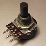
This is the scheme for a standard volume control. The component used is a potentiometer, often abbreviated to “pot” or sometimes “potmeter.” The photo at the right shows a typical model. It consists of a track of graphite connecting the two outer pins, and a taper which slides across this track as the shaft is turned. This way, the impedance between the middle pin and the outer pins can be varied between zero and the total impedance R of the graphite track. Impedance expresses the relation between voltage and current and is measured in Ohms, indicated with the symbol Ω. More specifically, impedance is a measure for the degree to which current is ‘impeded’ given a certain voltage. Higher means that less current will flow for the same voltage. Under certain conditions, impedance is the same as electrical resistance.
The potentiometer in the scheme is viewed from the bottom, i.e. with the shaft pointing away from you. In this configuration, the volume will increase when turning the knob clockwise.
The pot's impedance value R is important. Too low and you will lose signal amplitude even with the control at ‘max’, too high and the useful range of the volume control will be reduced and the circuit may become more sensitive to noise. A good rule of thumb is to use a pot with a value about 10 times the impedance of what is connected to its input. If that input is a pick-up, you can find its impedance in its data sheet, or measure it with the right equipment. Of course, when this input consists of more than just a single pick-up, you will need to correctly calculate the actual input impedance, which I will not explain in this introductory text. When multiple pick-ups may be switched in various combinations and this mix serves as input for a pot, the resulting total impedance will vary and you will need to use a pot R value that is a compromise. In this case it may be preferable to pick a conservatively high value over a low one. This problem can be avoided by using active circuits, but that is outside the scope of this text.
For guitars, traditionally potentiometers of around 470 kΩ are used. This is partially due to the legacy of high-impedance vacuum tube circuits, but is not entirely unreasonable given that guitar pick-ups can have impedances of up to 16 kΩ. 470 kΩ is very high compared to modern standards however, and should be avoided. Try to stick to the 10× rule instead.
As you can see in the figure, the metal casing of the pot should be connected to your circuit's ground. If your pots have an all-metal casing and are mounted on a conducting plate, it suffices to ground one (and only one) of your pots' casings. Both the plate and the housings of all other pots will then automatically be grounded. Otherwise you'll have to solder a ground wire to each of the pots' housings. The reason why only one pot should be grounded if they are all connected through a conductive plate, is that you must avoid making loops in the ground circuit: ground loops are a source of noise. The ground circuit should be wired in a ‘star’ or ‘tree’ configuration.
Important: you must always use logarithmic potentiometers for audio circuitry like this. This is indicated by “LOG B” or “B” on the pot's housing. For this reason such potmeters are also sometimes referred to as “audio taper” pots. Do not use linear potentiometers, with “LIN A” or “A” indicated. The reason for this is that the human ear has a logarithmic response (in both volume and frequency). A “B” pot will actually make the amplitude vary (approximately) according to an exponential curve if you turn the knob clockwise, and this is exactly what we need. There are also “LOG C” potentiometers (so-called ‘antilog’), which are reversed compared to B pots. This is certainly not what you want.
Tone control
A standard tone control consists of a Resistance connected in series with a Capacitance. Hence the name “RC filter,” which is one of the simplest low-pass filters possible. The way this works is as follows: the ability of the capacitor to conduct electricity increases with increasing frequency. By connecting the capacitor between signal and ground, high frequencies will be “short-circuited” and low tones will pass. Mind that the R from the RC filter is not the potentiometer in this circuit, it is the equivalent series resistance of the incoming signal. The pot merely allows to control the degree to which high tones are ‘grounded’.
An RC filter as shown above has a cut-off point fc that can be calculated as fc = 1/(2πRC). Roughly spoken, frequencies below this point remain unaffected and frequencies above it are attenuated. The required capacitance to obtain a desired fc given a certain R is given by C = 1/(2πRfc). Mind that the pot's impedance does not play a role here: fc will not be affected by turning the tone knob, only the degree of attenuation will.
When connecting a single pick-up to this control, R in the above formula is the impedance of the pick-up (which is not the same as its DC series resistance, but you may assume it to be for simplicity's sake). When connecting something more complex like a combination of pick-ups or the output of other circuits, things are more complicated and you will again need more advanced knowledge about electronics to calculate the exact values. For those without such knowledge or with formulaphobia: don't worry. You can get pretty far through a few simple rules of thumb and some experimenting. The formulas show that for lower impedances, you need to use higher capacitances to obtain the same frequency cut-off. To lower the cut-off point (remove more high tones), you need to use higher capacitance values as well.
Capacitance is expressed in ‘micro-Farads’ (µF), or ‘nano-Farads’ (nF) for smaller values, with 1 µF = 1000 nF. In a typical guitar circuit you may find values around 20 nF, which would produce a 1 kHz cut-off for an 8 kΩ pick-up (e.g. a humbucker). For a 3 kΩ pick-up like a single-coil Stratocaster, a 50 nF capacitor would be required to get the same 1 kHz cut-off. The good news is that the kind of foil and ceramic capacitors with small values like these, are both tiny and dirt cheap. This means that instead of meticulously calculating everything, you might as well just go to the nearest electronics store and buy a whole set ranging between say 10 nF and 330nF, and experiment to find a value that produces a good sound, which in the end is the only thing that really matters.
The potentiometer value Rpot and type (i.e. Log B) must be chosen in the same manner as for a volume control. Again, too small a pot value will cause a noticeable loss of trebles even with the control “off”. There are other ways of creating a variable resistor from a pot than shown in the figure, e.g. by just grounding only the middle pin, or grounding the rightmost pin and connecting the signal at the middle pin with the remaining pin unconnected. This is not recommended however, because the unconnected pin of the pot will be ‘dangling’, potentially acting like a tiny antenna for noise signals. The more grounded stuff in your circuit, the less risk of noise.
Pick-up selector switch
There are several ways to make a pick-up selector circuit. For instance you could provide a mini-switch to turn on/off each pick-up. But if you want to keep the amount of clutter on your guitar as low as possible, it may be a better idea to use a single selector switch. The most popular model is the Stratocaster switch, which has five positions. If you have three pick-ups A, B and C, this allows you to switch your pick-ups in the combinations A, A+B, B, B+C, and C. How this works is illustrated below. You can also use the switch with two pick-ups and additional tone control circuits.
As you can see, the switch consists of a rotating metal plate which is always connected to one contact “S” (the ‘signal out’ of the switch), and can be connected to one or two of the other contacts at the same time. Fun fact: originally the switch only had three positions, but people figured out that by shifting it in between positions, the signals of two pick-ups could be combined, producing more variations in sound. Therefore eventually the switch was manufactured to have this feature by design.
This switch has a series of contacts at each side, theoretically alowing to switch stereo signals, two separate circuits at the same time. Whether you'll be using both sides of the switch depends on the rest of your configuration. If you only want to use the switch to select pick-ups, you only need one side. It may then be a good idea to connect the corresponding pins of both sides together, resulting in “double” contacts. This will reduce the risk of crackling during switching as there is less risk of a bad contact. An example of a circuit where both sides are used is the standard Stratocaster circuit, as shown below.
This circuit uses only one capacitor with two potentiometers. The capacitor is connected between ground and taper pins of both pots. Depending on the position of the switch, none of the pots is used, only one, or both at the same time.
A selector switch may be redundant if you have separate volume controls for each pick-up, which would allow to turn off a pick-up by setting its volume to zero. But of course this is slower than a switch and it will wear out the potentiometers more quickly.
Active circuits
An active circuit contains some form of signal amplification, therefore it requires external power. For a guitar the only practical power source is a battery, although it would be possible to feed DC current through one channel of a stereo guitar cord. In its simplest form, an active guitar circuit consists of a classic passive circuit, with an amplifier between it and the output jack. Besides providing a stronger output signal, this may seem pretty pointless, but it isn't. A guitar with only a passive circuit will sound different depending on the impedance characteristics of the amplifier or even just the instrument cable it is connected to. Especially tone controls will behave differently. By ‘buffering’ the output with an amplifier, the output sound will be much more consistent.
Another advantage of active circuits is that they can be more versatile, in theory you could put an entire effect unit inside your guitar. The only considerations are power usage (you don't want to drag along a whole arsenal of batteries), and noise. Active circuits have a high risk of introducing additional noise, which will be worse with more shoddily constructed circuits. When incorporating an active circuit in your guitar you may still want to provide a switch that allows to bypass the active part, for in case you run out of power at the wrong moment or if you simply want to feed the raw output of your guitar directly to the amplifier. And, don't forget an on/off switch. You can create an automatic on/off switch with a stereo output jack and a mono guitar plug, by using the ground segment of the plug as the switch.
My second guitar's circuit
This circuit combines all of the above (except active circuits), plus some extra features. The switches S1 to S3 are part of the potentiometers, which are “push-pull pots.” This means they have a built-in switch which can be controlled by pulling or pushing the pot's shaft. The switches are configured here to use either both coils of the humbuckers (normal mode), or only one coil, which gives a clearer sound (but more hum).
The switch S4 is a phase switch, which allows to reverse the middle pickup's phase. When the selector switch is in position 2 or 4, this results in a distinctive sound, often used for “surf”-type songs.
As you can see, this circuit uses the tone control method I previously advised against. This is because it was already soldered when I bought it (it actually is part of an old guitar), and I didn't yet have the time to change it. Besides, since the entire circuit is encapsulated in a cage of grounded foil already, the risk of the pots picking up interference is very small.
Only one side of the selector switch is used, but both sides are connected as mentioned above. Despite this, the switch did start crackling annoyingly after a few years. This can be fixed by spraying the contacts with contact cleaner like Servisol Super 10. The same goes for potentiometers. If using contact cleaner doesn't help on crackling pots, they may be worn out and need to be replaced.
Danger Will Robinson! Some safety concerns…
Coming back to the topic of the ground in electronic circuits: mind that not just all parts in your guitar's circuit should be grounded to minimise noise: ideally all metal parts should be grounded. This may be impossible for some disconnected parts but the farther they are away from the circuit, the less influence they have anyway. By far the most important large metal parts are the strings, because they are very close to the pick-ups. If you don't connect the strings with your circuit's ground, your guitar will produce an annoying amount of noise and hum as soon as you touch the strings. So you should connect your circuit's ground to the bridge, which (being metal itself) will ground the strings too.
The problem with grounding, especially grounding the strings, is that there is an increased risk for electric shocks. Many an artist has received shocks while simultaneously playing the guitar and singing into a metal microphone because the microphone's outer casing was on a different voltage than the guitar. When the difference is really large, a large current can flow with potentially lethal consequences. I do not recommend disconnecting your strings from the ground as this could make your guitar so noisy that ie becomes unusable. Instead, you should definitely make sure that all stage equipment is connected to a single grounding point or use isolation transformers where necessary.
There is a ‘trick’ which involves connecting the bridge with the circuit's ground through a capacitor instead of a wire. If the capacitance is large enough, this will effectively filter out hum and noise without allowing the flow of a large continuous low-frequency current (remember: capacitors block DC currents). This has two disadvantages however: the first is that the most obvious noise will be due to 50 Hz or 60 Hz mains voltage, therefore a capacitor large enough to ground these frequencies will also pass lethal mains current. The second is probably even worse: capacitors tend to short-circuit when subjected to too large a voltage, which is often also the moment when things get dangerous.
Go back to the guitar page
Go back to the electronics section of the guitar page