Why I Can't Give You STEP Files of My Designs: Solids vs. Meshes
This article explains the difference between solid-based and mesh-based 3D modelling. I'm mainly writing this because people endlessly keep asking me for STEP (STP) files of my designs, which do not exist because I model everything using meshes in Blender (or OpenSCAD, which despite being solid-based, also only outputs meshes). This article explains why it is easy to convert a STEP model into a mesh, but is generally impossible the other way round. It also gives a few hints for solving and avoiding problems with mesh-based models.
In a nutshell
A STEP file describes a 3D shape by composing it from solid volume primitives like cubes, cylinders, and the like, on which certain operations can be performed (like cutting, drilling, …) The STEP file format originated from the need to program CNC milling machines in a standard way, but evolved towards more general manufacturing. In the end though, it aims to represent something that could in theory be physically manufactured. If you design something in SolidWorks or a similar CAD program, you are usually creating solid models that can be exported to STEP. The fact that the models must always represent something physical, puts a limit on what can be represented. A look at the Wikipedia page about STEP reveals that the format leaves much to be desired when it comes to liberty of use and interoperability.
A mesh file like STL on the other hand, or what is created in typical 3D modelling programs like Blender, describes 3D shapes as a collection of surfaces in 3D space. In STL, the surfaces are limited to triangles, and everything is built from sets of triangles. This kind of representation originated from computer graphics, where the primary goal was to visualise objects. This means a mesh-based model does not necessarily represent a 3D volume. Only if a mesh is said to be ‘manifold,’ it is certain to represent a shape that could in theory exist in the real world. Mesh-based models offer way more freedom than solid-based models. It is always possible to convert a solid-based model like STEP into a mesh, but in general it is impossible to convert a mesh back to a solid model.
Because I model everything in Blender and OpenSCAD, all my models are mesh-based, and I cannot give you a STEP file for any of my models because there is no solid representation, although I do my best to always ensure my models are manifold. If you want to edit one of my models, your only options are to rebuild them from scratch in your solid-based CAD program (which may be near impossible for certain models), or just learn to edit mesh-based models in a program like Blender, and/or how to program things in OpenSCAD.
Solids versus Meshes
To illustrate the difference between the representation typically used in STEP files or other file formats that have their roots in the CAD world, and the representation used in STL files or other formats that originated from the computer graphics world, I have created the same scene consisting of 2 joined cylinders in both representations.
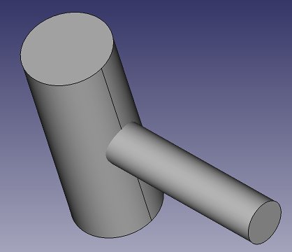
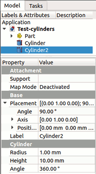
The above shows the scene as I created it in FreeCAD. What is typical about this CAD program representation, is that I have merely specified that I wanted 2 cylinders with specific dimensions, locations, and orientations. This also is how they are shown in the model overview. I can edit the radius and height of the cylinders and they will change accordingly.
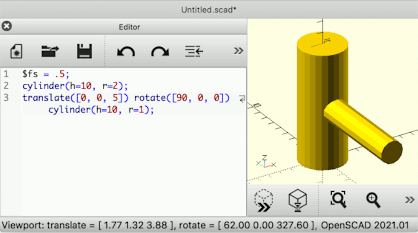
OpenSCAD takes this to another level. It has no menus or object trees for constructing and navigating a design. Instead, you need to program it entirely from source code. This gives it a steep learning curve, but makes it very suitable to generate parametric models. In another article on my site, I describe how to use its Customizer interface. Despite the fact that OpenSCAD works with solids though, it has no way to export to solid-based file formats, at least not at the time of this writing. It only exports meshes.
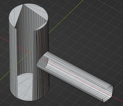
Now let's consider mesh representations. I can create “exactly” the same scene in Blender as above, by adding 2 cylinders with the same radii and heights, positions, and rotations. In Blender however, there is an immediate obvious difference: I also need to specify the number of segments. In this case, I chose 64 for the larger cylinder and 48 for the smaller one.
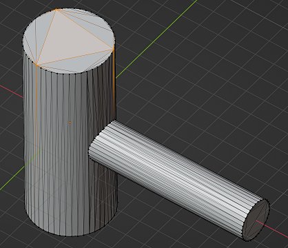
After creating the cylinders, as far as Blender is concerned, they are no longer cylinders but meshes, just like most other things that are meant to be a visible scene object. It are all polygons constructed by connecting 3D points. Instead of true cylinders, what Blender actually produced are two sets of connected rectangles arranged in a circular manner and capped by approximated circles. This is why I had to specify the number of segments up front. It is possible to change parameters like position, rotation, width and height, but it is not possible to explicitly specify a new radius, because there is no such thing as a radius for a general mesh. It is not possible either to change the number of segments. That can only be done by deleting the cylinder and creating a new one, or applying certain modifiers to the mesh.
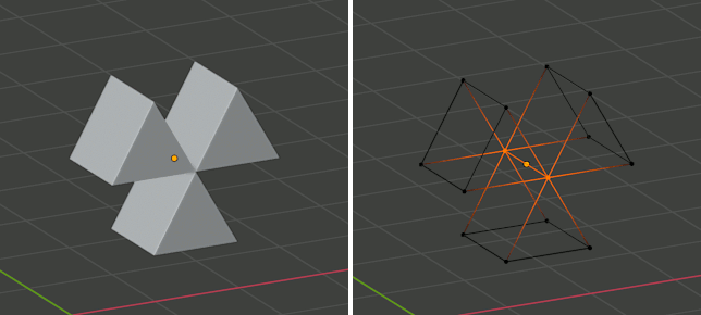
The immediate loss of the identity of the object after it has been created, is an obvious disadvantage of mesh-based modelling, as is the need to commit to a certain resolution at the time of creating each part. An advantage however, is that the mesh can be manipulated in ways that would be impossible with a representation limited to primitive shapes. For instance we can select some of the triangles the mesh is built from and delete them, which makes it all the more obvious how the shape is really only a collection of triangles in 3D space.
The above is an example of a mesh that no longer represents a true 3D shape, because it has ‘holes’ in it, making it merely a surface that has no thickness and no volume. Such model cannot be 3D printed. To turn it back into a solid printable model, the holes need to be filled, or some other operation needs to be performed, like giving the entire surface a certain thickness, for instance with Blender's ‘solidify’ modifier.
The above images again make it obvious why it is usually trivial to go from a STEP-like representation of a shape to a mesh representation. This involves choosing a certain resolution, and the conversion will then ‘render’ all the solid primitives into meshes built from collections of 2D surfaces. The inverse is generally impossible. It suffices for me to pick a single vertex (3D point) of my cylinder mesh and move it around, and the shape will no longer represent a cylinder and cannot be represented as a simple primitive in a STEP-like file. Much more extreme transformations can be applied to meshes, that make them impossible to describe as combinations of primitive shapes. Again, this is why I cannot give you a STEP file for any model that I have designed in Blender.
Insisting on working with STEP files for a design to be 3D printed, is a bit like insisting on sticking to classic 2D technical drawings for a building to be constructed. Sure, it will work because that was how it has been done for centuries, but it imposes limits for no good reason. Designing all the contemporary fancy building shapes with curved surfaces and protruding elements becomes very hard, if not impossible. The same goes for 3D printed objects and STEP files versus a mesh-based description. The whole idea of 3D printing is that pretty much any imaginable shape can be printed, not only those that can be modelled using tools and workflows intended for milling machines or other production processes that manipulate existing chunks of material instead of building up arbitrary shapes from scratch.
If you only came to this page to know why I can't give you STEP files or what a mesh-based design is, you can stop here. If you want to know more about the peculiarities of designing good mesh-based models, read on.
What is a Manifold Mesh?
Since one of the most common file formats for sharing 3D models is STL, a mesh-based format, it is not uncommon to bump into models that are said to be “non-manifold,” and these can be problematic to print. I bet there is a detailed mathematical definition of what it means for a mesh to be manifold, but in my own words:
A manifold mesh is a mesh that unambiguously represents a set of disjoint closed volumes.
Given this definition, a mesh derived from a solid shape representation model is always manifold—in theory. In practice, flaws in the routines that render the mesh from the model can still introduce non-manifold errors.
The last example shown above, where I intentionally made huge gaps in the model, is a very obvious non-manifold mesh, but it can be more subtle. Each surface in a mesh representation has an orientation, which means that one side represents ‘inside’ and the other ‘outside.’ This is why even an apparently closed shape can still be non-manifold, if for instance one of its triangles is flipped w.r.t. the others. Depending on the software, a mesh that is entirely turned inside-out may either be considered manifold (for instance Blender won't complain about this), or not (PrusaSlicer will complain). Strictly spoken, such mesh is manifold according to my own definition because it represents the entire universe as the closed volume, with the mesh being the only open space in that volume. But in practice, avoid inside-out meshes to avoid trouble.
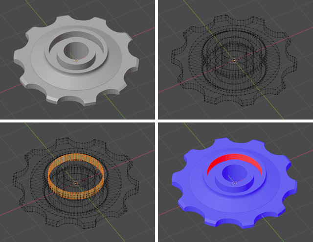
In Blender, there are a few ways to find out if a model is not manifold. The most thorough way is to switch to wireframe view, enter edit mode (usually by pressing the tab key), use vertex select, make sure nothing is selected, and then use Select → Select All by Trait → Non Manifold. Any vertices that are part of a non-manifold structure will be selected. If the mesh is manifold, the ‘Verts’ count shown in the toolbar will stay at 0. If not, you should be able to find the problematic areas by looking for selected points, although this is not always easy with complicated models.
A faster but less complete way is to enable ‘Face orientation’ in the Overlays. It will give all outside faces a blue colour, inside faces a red colour. You should see no red at all if your model is manifold. Red areas could indicate flipped surfaces, or holes in the model. If it all looks blue, there is no guarantee that it is all manifold, but at least there are no glaring faults like the one shown in the above image.
Fixing Non-manifold Meshes
Fixing non-manifold meshes is generally not trivial. You could attempt to run the mesh through some automatic repair tool, but my overall experience with such tools is that they are to be avoided. They will whack the model with some generalised strategy and will often degrade the whole model, even in areas where it had no problems to begin with. And even then, the result sometimes still is not manifold. The only way to fix a non-manifold mesh without losing detail, is to do it manually so you know exactly what is wrong and what you are doing to fix it.
Blender is an adequate tool to fix non-manifold meshes if the problems are not too numerous. In the above example, if the problem is merely that some surfaces are flipped, it should suffice to select all vertices, and then recalculate normals (default shortcut key ‘N’). If this does not suffice, I usually do the following to start cleaning up the model:
- Select all vertices in edit mode.
- Mesh → Clean Up → Merge by Distance, and use a merge distance that is sufficiently smaller than the smallest details in the model (the default is usually OK).
- Mesh → Clean Up → Degenerate Dissolve, and keep repeating this until it no longer reports it removed anything.
When importing models from STL files or other sources into Blender, I always perform the above procedure, followed by application of a ‘decimate’ modifier set to ‘Planar’ with an angle limit of 0.5°. This yields relatively clean models without visible loss of detail, and makes it easier to fix any remaining problems.
Quite often the above procedure will already clean up the model enough that it becomes manifold. If it doesn't, at least it will reduce the complexity and make it slightly easier to manually fix the remaining problems. Unfortunately there is no general strategy to fix non-manifold structures. The only thing you can do, is rely on the ‘select non-manifold’ operator, as well as Select → Select All by Trait → Interior Faces, to hunt down the flaws, and then do one of the following things:
- Remove loose vertices, lines, and faces that are not part of an outside shell.
- Split up structures where a single vertex, edge, or face is shared by multiple separated volumes.
- Fill holes and gaps.
Ensuring your model is manifold should always be a final step before exporting it to STL files that will be uploaded to a public site.
Avoid Creating Non-Manifold Meshes
The best way to avoid problems due to non-manifoldness is not to produce non-manifold models in the first place. A very common way of introducing non-manifold errors is to perform Boolean operations between objects without ensuring sufficient margins. This is not specific to Blender, every CAD program has this risk, also the solid-oriented ones are likely to produce dodgy meshes when exporting an STL file from a solid model that is poorly constructed.
Performing Boolean operations is a bit like using a milling machine (when subtracting or intersecting), or welding (when joining). When performing those physical operations with real machines, one should avoid situations that are borderline with respect to where surfaces meet, and one should not expect instant perfectly joined surfaces when fusing two things together. You wouldn't mill away 0.01 mm of a surface that is already almost flat, because the result will likely be ugly. Neither would you have your tool extend exactly as far as the edge of the material to be removed. You would always provide a comfortable margin.
When translating this principle to software, you should never try to subtract or join shapes using Boolean operators while the objects to be combined sit exactly against another, or the subtracting object extends exactly as far as the part you want to cut away. In a 3D model, “exactly” often is not as exact as you might think, and the result of the subtraction operation is likely to be a lot of rubbish that results from rounding errors.
Therefore, a few rules of thumb:
- When doing a subtract or intersect operation, always make sure that every end of the object that subtracts or intersects is either completely enclosed by the other object, or sticks out from it by a margin that is visible without having to zoom in to a ridiculous level.
- Avoid performing a Boolean operation between shapes that share a face, edge, or vertex.
- When doing a union operation, never try to join surfaces such that they would become one single flat surface or have an edge in common where they meet. If you want this kind of result, it is better to join 2 objects that are too large, and then cut away the final surface with a subtract operation—indeed, again just like you would often do with welding and milling in the physical world.
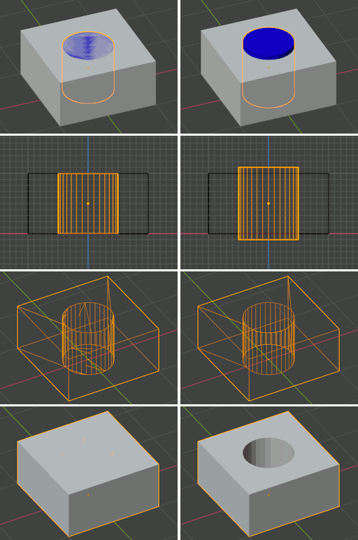
I have illustrated this in the image below, where a cylinder is subtracted from a box. I did use the ‘fast’ Boolean setting in Blender, the ‘Exact’ one produced a manifold result in this case, but it can still fail in less trivial cases. In the top left image you can see the kind of typical ‘dithering’ effect that occurs when two surfaces coincide, this is always a telltale sign that you should be adding margins somewhere.
The above rules cannot always be followed. Sometimes you need to make a circular hole in a cone-shaped thing or something, and there will be edges and maybe even vertices intersecting. Luckily the Boolean operators in Blender have improved over the years, and they will usually cope well with such situations, but they will still produce garbage when trying to combine objects that share faces in the exact same plane. The Boolean engine in OpenSCAD is even better, but it can still be pushed too far and produce garbage when doing unwise things. Therefore it is always a good idea to pretend you are actually welding and milling, even in OpenSCAD.
Another way to look at it is this: if you would slightly move one of the two objects in any direction, and this would suddenly result in a totally different result (for instance a union operation no longer actually joins the parts, or a hole caused by a subtraction suddenly becomes sealed), then you are at risk of producing a dirty non-manifold model. Provide enough margin such that even if the shapes would slightly move relative to each other, the overall result of the operation does not change.
Next to Boolean operators, in Blender there are many other opportunities to generate a non-manifold mesh. If you're about to do something that feels like it should be impossible in the real world, expect results that are likely to be incompatible with physical 3D printers as well.