A Subwoofer That Fits in a Backpack
Intro
Most people know subwoofers, and it used to be commonplace to imagine huge boxes with huge speakers and/or exotic tubing protruding from them when the term subwoofer is mentioned. It is a fact that to reproduce really deep bass sounds, a large construction is the easiest solution. This is formulated in “Hoffman's Iron Law,” which roughly spoken states that one can never pick more than two out of these three properties for a speaker cabinet:
- high efficiency,
- deep bass response,
- small size.
In other words, the only way to get really deep bass from a really small loudspeaker, is to pump ridiculously large amounts of power into it. Every speaker builder thinks they can circumvent this law at some point and they try, and fail. I didn't think I could circumvent the law, I just accepted it and built a ridiculously small cabinet that produces a very satisfactory amount of bass, with an inevitable, but not prohibitive low efficiency.
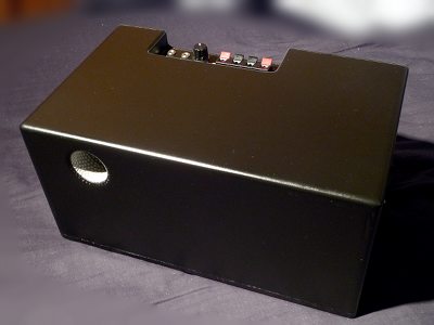
The goal was to have a truly portable 5.1 sound installation, when combining this contraption with two sets of small satellite speakers and a ghetto-blaster as center speaker. The smallest mainstream 5.1 sound systems commercially available still have a crummy subwoofer that is as portable as a desktop PC. There are some tiny high-end mini subwoofers but they are outrageously expensive. They rely on exotic custom-made drivers and amplifiers that can handle the insane power required to obey Hoffman's law. What I wanted is an affordable subwoofer made from readily available components, with included 5.1 decoder and front channel amplifier, that fits in a regular-size backpack. In other words, the whole system should not be larger than a small shoebox. This sounds impossible, but it proved possible with a bit of luck, skill, a healthy dose of engineering and a bit of compromising.
Acoustic Design
There are many possible designs for loudspeaker cabinets, so the first important choice is what kind of so-called alignment to use. The goal is to get the deepest possible bass for the smallest possible size, without requiring impossible amounts of power, using reasonably-priced components. Thiele & Small have derived formulas to describe low-frequency behaviour for designs based on closed and ported boxes, where the actual shape of the box is mostly irrelevant. With other designs like horn speakers or transmission lines, the shape of the box is very important, but modeling such designs is much harder. They are also typically rather large, therefore I restricted my search for a suitable design to the following ‘classics’:
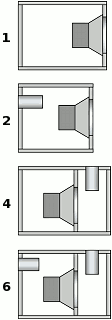
- First order: a simple closed box. This is easy to build and has very good acoustic properties. However, to get any appreciable bass from such a design either a large box with a large loudspeaker is required, or a smaller box with an exotic type of loudspeaker. This is not an option since I wanted to use off-the-shelf loudspeakers.
- Second order: a ‘vented’ cabinet, where the inside of the box is connected to the outside world through a ‘port,’ typically a tube. When designed properly, this tube will cause a resonance at the lower end of the speaker's frequency response, effectively extending it. Most people know this alignment as bass reflex. This is a good candidate for what I need.
- Fourth order: a closed loudspeaker cabinet encased in a ported box, which simulates a band-pass filter. Design is harder, but it allows deep bass in a small enclosure, making it also a very good candidate.
- Sixth order: the same as above, but with an extra port that connects the inside of the loudspeaker to the outside world. The benefits of this alignment mostly don't offset the difficulty of properly designing and tuning it, and having two ports exacerbates the risk of parasitic noises.
In other words, the choice was down to either a second or fourth-order design. I had already made a quite successful miniature subwoofer based on a fourth-order design. It was an experiment and I hadn't even properly calculated anything about it, mostly due to the simple fact that it was part of a ‘boombox’ completely built from scrap materials including the loudspeakers for which I didn't have any T&S parameters. Yet, after some ‘wet finger’ tuning it performed surprisingly well, which gave me condifence that I could make something even better and smaller with proper modeling. This experiment gave me a slight preference for a fourth order design.
The only type of loudspeaker that would fit together with all the other components inside something as small as a shoebox would be an 80mm driver, the format often used in PC ‘multimedia’ loudspeakers. So, I collected the parameters for suitable commercially available 80mm loudspeakers that are reasonably priced. The highest power handling to be found in this category is about 30W RMS, which is OK for a small subwoofer for small rooms. I really wish there would be more powerful speakers in this form factor. I'm pretty certain some manufacturers make such speakers, but only to incorporate them in commercial proprietary miniature subwoofers, not for individual sale.
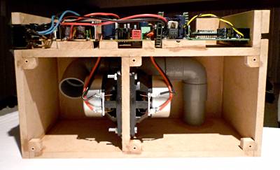
Isobaric Set-up
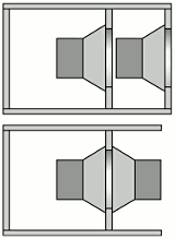
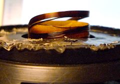
In my quest to minimise enclosure size, I stumbled upon a strange concept that allows to effectively halve the equivalent volume (Vas) for a given loudspeaker. In practice this means that the volume of the enclosure can also be roughly halved. The catch is that two identical loudspeakers must be placed ‘in series,’ such that the air in between them stays at the same pressure. This configuration is therefore often called ‘isobaric,’ ‘isobarik,’ or ‘push-pull’. In a certain sense, it turns the two loudspeakers into a single equivalent speaker that has twice the driving force. The most compact way to implement it is to mount the two speakers with inverse phase against each other as shown in the bottom part of the image. It is not often used, for the simple fact that it doubles the costs and power requirements for the amplifier. But in my case, those were subordinate to the strict requirement of minimal size.
The next step was an endless series of simulations. The formulas to predict optimal enclosure volumes for given specifications proved useless, often giving negative, huge or impossibly small volumes. It was obvious that I would need to allow more ripple in the passband than usual to get any amount of bass worthy for a subwoofer. Therefore I switched to just simulating frequency responses for reasonably-sized enclosures of various designs with the few suitable candidate speakers in isobaric configuration.
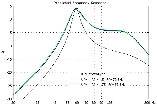
I finally settled for a fourth-order design with a closed volume of 1.5 litres and a ported volume of 1.1 l, tuned around 72Hz. With two Visaton SC 8 N drivers in isobaric configuration, this produced the lowest bass roll-off and ‘flattest’ band-pass response, albeit with an unavoidable rather strong resonance peak around 60Hz. It's all a big compromise, I could have gotten a flatter response but it would be much less efficient. I chose this curve because of the following reason. In the meantime I had found the correct parameters for my first experimental prototype, so I computed its frequency response. It proved to have a much larger resonance at 60Hz as well, actually the whole response was just a peak at 60Hz without any platform around it (see the graph). Yet, it sounded pretty good, probably because it happened to complement the bass roll-off of the other speakers. Given that the new design was much nearer to a flat response, it should sound even better. Remember, the main goal is to get backpackable good bass during movies, not perfect Hi-Fi reproduction.
A close contender was a second-order design with a volume of 4 l, which has roughly the same low-frequency limit without the resonance, and is actually more efficient overall. However, I chose the fourth-order because:
- The low-frequency roll-off is less fast, meaning there will be slightly more deep bass,
- The fourth order has high-pass filtering on its own, easing the design requirements for the electronic filters,
- The fourth-order design is a completely closed box with only the port tube connected to the outside world, making it much more transportable than an isobaric second-order box where one of the speakers would be awkwardly mounted on the outside, requiring extra protection.
- The second-order design is larger, especially with the extra construction to protect the outside speaker.
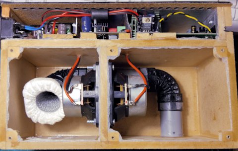
Serious Plumbing
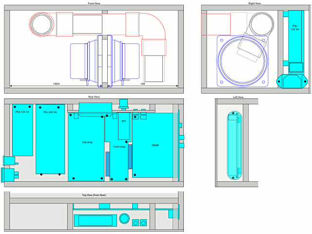
The only major drawback of the fourth-order design proved to be the dimensions of the port. For the minimal acceptable inner diameter of 28 mm PVC tubing (32 mm outer diameter), to avoid excessive turbulence, the port needs to be around 30 cm. That is longer than any of the dimensions of the entire final product, meaning that the tube needs to be folded in some way. It took me a lot of 3D puzzle work to come up with a design that houses the two speakers, two compartments, and 30cm of PVC tubing, but in the end I arrived at something with two bends.
Doughnuts and Golf Ball Dimples
If it isn't already obvious: this project was not a walk in the park. It is more like an exercise in pushing the limits of the impossible. Normal people would have abandoned the idea of cramming two loudspeakers, a 5.1 decoder, two power supplies, four amplifiers and 30 cm of tubing in a shoebox, but just look at my other articles on hardware and you'll see that I don't care about “normal.” I knew such a long narrow tube with two bends would have a high risk of producing wind noises, but I had a few tricks up my sleeve. First, I fit the inside end of the tube with a ‘doughnut’ shape, to make the entry and exit of air into the tube as smooth as possible.
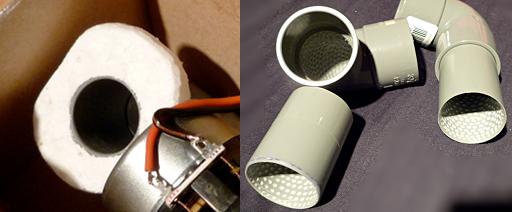
Next, I used some physics borrowed from golfing. Golf balls are covered with a dimpled surface because it reduces aerodynamic drag (there's a less serious application of this to be found elsewhere on this site). It effectively causes the air to stick longer to the golf ball before breaking free (so-called boundary layer separation) and causing turbulent vortices at the port exit. Turbulence causes noise and reduces efficiency, two things I want to avoid. Therefore I turned the golf ball idea inside out and covered the entire inside of the port with dimples. (In retrospect, this was probably pointless, see the comments below.) I did this with the ball-shaped milling tool of a Dremel drill. Needless to say it took a while. I didn't do any rigourous before/after tests to see how effective it is, but I later discovered that B&W also use this trick on their speakers (they call it ‘FlowPort’), so it must have some merit, especially given the fact that everything about my design is borderline. Don't waste your time adding dimples to a conservatively designed subwoofer port.
In June 2022, I performed 2 upgrades to the whole thing (yes, I am still using it after 11 years).
- First, I replaced the commercial PVC bends with custom 3D printed bends. The stock bends had an inner radius of zero, a sharp 90° transition. While staying within the constraint that the connecting sleeves had to be in the exact same positions as before, I could fit a bend with overall larger radius in the same space. This brought the inner radius to 9.5 mm, still not much but way better than a sharp edge. The effect was not dramatic because most of the noises were generated by the port's exit, but it did help to make the noise resonate less within the tube, making it less sharp.
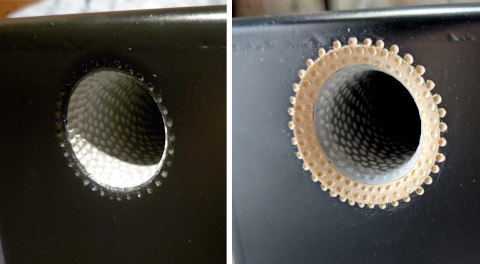
- I increased the radius of the port's exit. Originally it barely met the guideline of the radius being .2 times the port diameter, which is probably optimistic at these small scales anyhow. Therefore I raised the radius to .3 times the diameter (8.5 mm). I considered using a 3D printed part, but simply milling and sanding proved the easier option. This resulted in a very noticeable reduction of wind noises, and I left it unpainted because it looks cool.
As for the dimples, in the meantime I have figured out that roughening the entire inside of the tube was rather pointless and maybe counter-productive. Adding dimples (or similar boundary layer separation mitigations) where unneeded, could actually increase parasitic noises. Boundary layer separation only risks occurring when air travels across a convex surface while losing velocity and gaining pressure, like when exiting a flared port. This means it is only useful to add dimples or other tricks to promote a turbulent boundary layer at such locations. Hence I re-dimpled the newly widened radiused exit, because there it makes total sense. I also added dimples to the inner radius of the new bends, although I am not entirely sure whether it is needed there.
Electronics
After the squeezing of relatively large objects into small confined spaces came the squeezing of small electronics on small PCBs. I wanted this whole thing as compact as possible, with all the following built into the box:
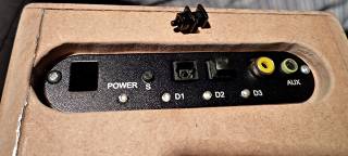
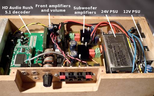
- 5.1 decoder: I found a small standalone AC3 and DTS decoder in the form of the HD Audio Rush, which I of course also hacked.
- Subwoofer amplifiers: due to the isobaric design, I would need enough power to drive the dual speakers. The most feasible is to use two amplifiers of preferably 30W RMS to get the maximum out of the speakers(1).
- Front channel amplifiers: I wanted to avoid a separate power source for the front channel satellites, which could therefore be simple passive speaker boxes connected to speaker terminals on the subwoofer/decoder box.
- Volume control: obviously, a surround system without a volume control would be pretty annoying. I needed a compact method to simultaneously control six channels. I settled for a 6-way potmeter with buffers. In retrospect I should have used a motorised type such that I could add a remote control, but there simply was not enough space.
- Power supplies: I didn't want to have to lug around external power bricks.
As for the subwoofer amplifier, the only real option to get 2×30W RMS with good efficiency in a small size is a class D design. After a long quest for the ideal chip amp I found the TPA3122D2 from TI. It is one of the few class D chips in a classic PDIP package. My SMD soldering skills have improved lately but I still shy away from large ICs with tiny feet, especially things with additional heatsink pads like most of the class D ICs. Moreover, PDIP can be mounted in a socket, hence easily replaced, which proved valuable when I blew up both ICs while doing something stupid while testing the board. When carefully examining the TPA3122D2's datasheet, you'll notice that it is only theoretically able to output 30W RMS at 8Ω. In practice the limited power dissipation of the PDIP package will trigger the overheat protection if the IC is subjected to a high load for a long time. To avoid this as much as possible, I mounted heatsinks onto the chips.

For the front channel amplifiers I used a more classic class B chip amp, the TDA1516CQ, mostly because I had two of these lying around, it requires very few external components, and I had already made a well-performing amplifier with its cousin TDA1516BQ. This gives 2×10W RMS for the front channels. In retrospect I could also have used a single additional TPA3122D2 but it would hardly have taken less board space. The outputs for surround and center are simple line-outs, because the rear speaker set and the ghetto-blaster have their own amplifiers. I created the PCBs for both this amplifier/volume control and the subwoofer amplifier with the toner transfer method.
Finding the right power supplies was as tedious a procedure as finding the right speakers, enclosure design or subwoofer amplifier. I needed PSUs that are small, efficient and sufficiently powerful. The previous experiment ran successfully on a switching laptop power supply, so I searched for something similar. (Audiophiles will scream when reading “switching PSU,” but they should already have gotten a heart attack when reading about cramming two multimedia speakers in a shoebox.) I needed 24V for the class D amps, and 12V for the rest. Actually the 5.1 decoder needs 9V, but I could derive this from the 12V. Eventually I used the power supply for an Asus EEE PC for the 12V, and a scanner power supply for the 24V.
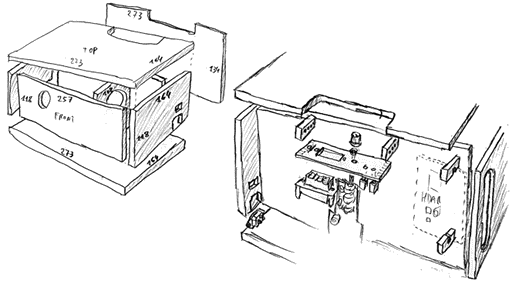
One Giant 3D Puzzle
With all components decided on, all that was left was designing and building the amplifier boards and stuffing everything together in a box made of 8mm MDF. Normal people would resort to an actual 3D program like AutoCAD for this, but I'm an oldskool engineer. I was trained to design stuff on drawing tables, so I just drew oldskool 2D projections in a drawing program. Of course, for a more complex shape I would go ‘3D’ but for something box-like like this, 2D plans are perfectly adequate. Of course, the volume occupied by the speakers and tubing must be taken into account when determining the dimensions of the chambers. The end result is a box of 27.3×16.4×13.4cm. The subwoofer part is 27.3×12.4×13.4cm.
Building the thing was not easy but compared to designing it, it was a breeze. Mounting all components really is a kind of puzzle, because it becomes impossible to mount certain parts if they aren't mounted before other parts. For subwoofers in general and especially tiny ones like this, airtightness is crucial. Leaks will cause noise, which can be very noticeable as I found out from my first experimental mini-subwoofer. To obtain an airtight seal while still keeping the possibility of servicing the inside of the sub, I used my classic foil-grease-and-silicone method, which means I glue aluminium foil to the lid where it connects with the box, apply grease to the foil, and then seal everything with silicone sealant. The grease prevents the silicone from permanently sticking to the foil, which makes it possible to re-open the box without destroying the seal or having to reapply the sealant.
Now, Does It Work?
Yes! It works and acts pretty much exactly as predicted by the formulas, it is amazing to see that the T&S formulas still apply to such an insane design. However, the whole thing inevitably gets warmer when in use for a while, and this changes the characteristics. Luckily, it changes them for the better. I can't explain why but when it is fully warmed up, it seems that the overall response gets smoother and deeper. Therefore I let the whole thing ‘warm up’ whenever possible.
The heat is also a problem, though: with the speakers packed in small enclosures that are also heated by the nearby electronics, they get quite hot. While playing one particular movie that had a louder soundtrack than usual with some very strong bass sounds, the lack of a remote control combined with laziness made me think: “ah well, it should handle it,” instead of walking up to the knob and adjusting it. A rattling sound at the end of the movie was the result. One of the speakers had had too much: an autopsy revealed that its voice coil had come loose. Although it is probably partly due to the amplifier clipping and subjecting the speakers to more than 30 W RMS, I suspect this might have been a manufacturing defect because the other speaker was still perfectly OK despite having undergone the same mistreatment. (However, that driver has the benefit of getting some cooling from the moving air at the port entrance.) Also, although the coil had visibly overheated, my forensic investigation revealed that this must have happened mostly after it had detached.
Of course I couldn't send off the massacred speaker to Visaton and hope to get warranty on it. Thanks to my decision to choose reasonably priced widely available components, I had a new SC 8 N two days later. With some extra ventilation holes for the electronics and a bit more care, this one should last longer—in fact it still is in perfect shape 11 years later. Nevertheless, I would be willing to pay a little more for a speaker that can cope with these extreme conditions and has more headroom above the 30W RMS rating of the amplifiers. If anyone knows of a manufacturer that sells 8 cm (or slightly larger) speakers with a large excursion that can handle more than 30W RMS, I am interested.
As expected, there is wind noise, but it is only audible when there is nothing but pure bass in the movie soundtrack at about 60Hz—the resonance peak in the response. This rarely happens and the noise is mostly masked by other sounds, and it got even better with the 2022 upgrade. I could probably further reduce the noise by equalising out the resonance with an extra filter, but it is hardly worth the effort. I did foresee an extra header on the sub board to plug in a filter circuit, but I doubt I'll ever implement it. Yet, next to removing the resonance it would have the advantage of reducing the load on the speakers a bit, but this would also reduce some of the ‘oomph’. Perhaps I'll experiment with it if I ever find enough time.
The long twisting tube has quite a few resonances at higher frequencies, which meant I had to make the lowpass filters in the electronics more stringent after all, so my idea of avoiding extra filtering had backfired a bit. In retrospect, the second-order design may have been not that bad after all because it required a much shorter tube. The bottom line is that this was a very interesting experiment and it works satisfactorily, but I do not recommend building it to anyone who wants a powerful subwoofer. If this prototype would break beyond easy repair and I would make a new one, I would go for HexiBase's design that uses a Tang Band W3-1876S driver. I would also put all the electronics in a separate box, with as nice-to-haves a remote control and a wireless link to all the satellite speakers, to make this even more portable and quicker to set up and break down.
Over the years it has become obvious that the 2×30 W rating is utopian. First of all, due to the isobaric set-up, it only really has the same output power as a single 30W driver, but again only in theory. In practice, the limitations of the long narrow port become prohibitive way before reaching anywhere near the maximum power. The wind noise becomes unbearable and the output is smothered by extreme compression and turbulence. I could probably have driven both speakers with a single 30 W 4 Ω amplifier. It is of course the name of the game, Hoffman's Iron Law cannot be beaten.
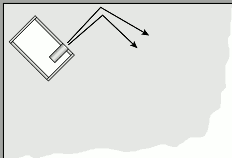
This makes the subwoofer only suitable for smaller rooms. However, a satisfying amount of bass can be obtained even in a medium-sized meeting room, by paying some attention to the placement of both the subwoofer and the audience. As usual, the center of the room is to be avoided and the corners prove optimal, but also the orientation of the box proves important. The best result is obtained with the port firing at a 45° angle towards the front wall. Perhaps this causes a bit of a horn effect, and an audience sitting near the back of the room will experience a pretty satisfactory bass output. Of course there are no bowel-shaking rumbles, but it surely punches above its weight for what it is.
(1): an amplifier with a 30W RMS power rating is actually capable of producing up to 60W average power when pushed into maximum overdrive, therefore I am indeed risking to burn out my speakers here (which already happened). But I want the subwoofer to be able to produce a clean output at the speakers' maximum rating without overdrive. I also took this decision in the hope of ever finding speakers with a higher power rating. If you're building your own sub and you want to minimise the risk of smoking your drivers, make sure their RMS power rating is twice that of the amplifier.