How does QTVR work?
This page provides detailed background information on the mathematical aspects behind (the now obsolete) QTVR panoramas. The technology may have been mothballed, but the science behind it lives on. It becomes quite technical after a while, so if you're allergic to maths you'd better stop reading at the end of the introduction.
Introduction
The trick of a QTVR panorama is to apply a certain transformation to a set of photographs in order to squeeze them into a single image which represents a 360° view of a certain scene. This scene can then be viewed by applying the inverse transformation.
How can this be achieved? A conventional photograph is a plain central projection of a scene onto a flat projecting plane. Because a photo is a flat plane itself, you see a perfect reconstruction of the real world scene (if you view the photo from the correct distance). So, to keep things simple, we could use a similar method for projecting our 360° panorama. But in this case, a simple plane won't do. If you think about shapes which can be considered, there are only two which suit our needs: the cylinder and the sphere. A cylinder is, in fact, nothing but a plane which has been bent and whose ends are stuck to each other. The sphere could also do and would even allow to make a 360°×360° projection, but this is far more complex, although successful implementations of such a system have been made.

How does this work?
A practical method for making a cylindrical projection of a scene would be the following: take a transparent plastic cylinder and a permanent marker. Go stand inside the cylinder and put your eye at the exact center of the cylinder. Now start drawing what you see onto the plastic, while staying motionless. The only thing you can do is rotate your head while keeping your eye at the same position, in order to draw the rest of the scene. When you have drawn everything over the full 360°, cut open the cylinder and roll it open onto the floor. What you now see, is a cylindrical projection of your scene.
You can re-experience the scene afterwards by restoring the cylinder, and then looking at it from exactly the same position as the moment you drew it.
In fact, this is how QTVR panoramas work. Of course there are no plastic cylinders and waterproof markers involved, but the principle is exactly the same.
Until QuickTime 5, QTVR was based on cylindrical projection only. Then “Cubic VR” was introduced, which does allow 360°×360° viewing, not by using a sphere, but a cube. This means the scene consists of 6 photographs placed onto a cube. From a certain point of view (especially the programmer's), this is simpler. For instance, the entire rendering can be done trivially by graphics hardware. But actually the requirements for the input photographs are more stringent, and in some cases it simply doesn't make sense to be able to see what's above and below you, so this system will never replace the cylindrical method completely. Because there is not too much to be told about projecting a scene onto 6 planes and then viewing this cube from the inside, I will only discuss the cylindrical projection here.
Let's take a look at the mathematics involved when projecting a 3D scene onto a cylinder.
Projecting a 3D scene onto a cylinder
Consider a cylinder with parametric equation in t:
(cos t, sin t, z)
This is a cylinder with radius 1 whose axis coincides with the Z-axis. In fact, we could take any cylinder, but this one will make our calculations a lot easier.
We want to project a scene, consisting of a collection of coordinates, onto this cylinder, and then roll it open to achieve a rectangular image. As with all projections, we first need to choose an eyepoint. This eyepoint must be on the axis of the cylinder. Again to simplify our calculations, we choose our eyepoint in (0,0,0). This may seem to limit our freedom of choosing a viewpoint, but the only thing you need to do in order to change your view is translate and rotate the coordinates of the scene until the cylinder and viewpoint are in the right position.
If we would need to do our calculations in Cartesian coordinates, we would kinda go mad. Luckily cylindrical coordinates exist, which are just perfect for our problem. In cylindrical coordinates, the equation of the cylinder becomes:
r = 1,
which is about the simplest equation one can get.
In most situations, the coordinates of our scene will be measured in a Cartesian system. To perform the projection we must convert these to cylindrical coordinates, which can be done with the following equations, for a point with coordinates (x1, y1, z1):
r = sqrt(x12 + y12)
tan θ = y1/x1 (watch the quadrant!)
z = z1
Now we're ready for the real thing. To project a point p onto the cylinder, we need to connect it with the eyepoint o and calculate the intersection s of the resulting line and our projecting cylinder (see image). Instead of setting up the full equation of the line and then combining it with the cylinder's, we can split up the calculation in the XY-plane on the one hand (intersection line-circle) and the RZ-plane on the other hand (intersection line-vertical line).
The calculation in the XY-plane is very simple and goes as follows:
Because all our coordinates are cylindrical, we already know the angle of the line which connects the point with the origin (eyepoint), let's call this angle theta (θ). The intersection with the circle doesn't even need to be calculated, by definition it is (cos θ, sin θ), or in polar coordinates (1, θ). Hence the coordinate of the intersection cylinder-line in 3D will be (1, θ, z).
To calculate z, we consider the plane formed by the Z-axis and the line going through the point and the viewpoint. In this plane it is easy to calculate z:
The equation of the line going through (r1, z1) is:
z = r*z1/r1
All we need to do is calculate the intersection with the line r = 1, which results in:
z = z1/r1
So to conclude: the coordinates of our projected point s on the cylinder are:
(1, θ, z1/r1)
What we need to do now is “roll open” the cylinder to get a flat image in (x, y). The only thing we need to do for this is omit the r coordinate (which is always 1 anyway) and consider the θ coordinate as an x coordinate. If we now plot the (x, y) coordinates we obtained, we have our cylindrical projection! The resulting image is 360 units wide if you used degrees for θ, or 2π units if you used radians.
The only problem is, to get a decent representation of a scene, a collection of points won't do. We need to connect these points with lines. And this is when a serious problem comes up: in a cylindrical projection, a straight line is not a straight line. One can see this very well in the following image.
This “deformation” is a result of the projecting and the rolling-open of the cylinder. To be more exact, non-vertical lines are projected to sinusoids, but I won't prove this here.
The major consequence of this is that, if we would simply connect the dots in our projection with straight lines, we would get a distorted projection, and the lines wouldn't look straight when viewing our projection in QTVR. A solution is to interpolate the coordinates, in order to decrease the distance between the points so that the curves are approximated by a lot of short straight lines. One could do a “dumb” interpolation, which just inserts a specified number of points between each two coordinates, but a “smarter” way of interpolating is to make sure that each time a maximum distance between two projected points is exceeded, enough points are put in between to decrease the distance between the points.
Another problem are lines which run across the 0° and 360° lines. If we simply draw a line between the two ending points of such a line, we get a line running through the entire picture instead of through the sides of the image. To avoid this, we need to determine when a line crosses the “seam” of the panorama.
If you look at the image at the right, which represents a top view of the scene, you'll understand that a line crosses the “seam” when two conditions are met:
- The line must of course cross the X-axis. In mathematical words this becomes: the product of the y-coordinates of starting and ending point must be negative: y1*y2 < 0
- The projection of the line in the XY plane must intersect with the X-axis at a position “in front of” the viewpoint, that is: with a positive x-coordinate.
Turning this last condition into a mathematical equation requires the equation of the line (x1,y1), (x2,y2) and x, the x-coordinate of this line's intersection with the x-axis. If you do the calculations, you should find the following equation:
x = (x1y2-x2y1)/(y2-y1) > 0
If both of these conditions are met, we need to draw the line in two parts: the first part from the starting point of the line to the intersection with the seam, and the second part from the other end of the seam to the ending point.
To illustrate this projection method, here are some projections of scenes, in both perspective and cylindrical projections.
 |
→ |  |
 |
→ |  |
 |
→ |  |
The last example shouldn't be surprising, because all points on the spiral are also points on a cylinder. So if one rolls open the spiral, one simply gets straight lines.
The program I used for this (PanoProjector) is available here, but it only works in HyperCard or the HyperCard player. In other words, it only works on old Macs, but if you have some programming experience, you should be able to create such a program yourself with all the info provided on this page.
In this program one can import a file containing a set of dots and/or lines, and then project it with various settings after translating or rotating at will.
Transforming a perspective projection to a cylindrical projection
Despite al those neat calculations, the method described above is not very handy when it comes to practice. In the real world, people want to make a panorama of real life scenes, not of an imaginary space which consists of coordinates connected with lines. One way of achieving this would be to build a special camera which would actually use a film bent into a cylinder. But because this is very hard (read: expensive) to make, we have to make a roundabout via the good old perspective projection. In fact, a complete set of perspective projections provides the same information as a panoramic projection, but in a slightly different form. The only thing we need to do is transform this set of perspective projections into a panoramic projection.
The word “set” is important, because you have to understand that it's impossible to make a panorama from just one ordinary picture. The reason for this is the fact that that a perspective projection only “snaps” what lies in front of it, and is within a certain viewing angle smaller than 180° (typically ±45°), while a panoramic projection includes everything in a range of 360°. The only limit of a cylindrical panorama is determined by the vertical viewing range.
An interesting remark about this is that if we would use a spherical projection, this problem would be gone too and we would have absolute 360°×360° freedom. Unfortunately, such projections are very hard to make because one cannot just ‘roll open’ a sphere like a cylinder (which has always been a problem for cartographers). There are methods to do this in a certain way (resulting in so-called equirectangular images), but these are rather complex. Therefore Apple chose a simpler solution to achieve 360°×360° viewing: instead of using a sphere, ‘Cubic VR’ uses a cube. This makes the rendering process pretty easy, but the image acquisition process harder, especially for the top and bottom faces of the cube.
Back to our cylinders!
Instead of using a cylinder for our panorama, we could as well take 8 photos of our scene at intervals of 45°, and then put these photographs in an octagonal cylinder. If you then look at those photos from within the construction, at the same position where the camera's focal point would be, you would achieve the same effect as with the real cylinder. But QTVR only works with circular cylinders. So to transform our set of photos to a panorama, we need to transform those 8 snapshots into one panoramic projection.
This is not as hard as it may seem. In fact, it's almost the same as projecting a 3D scene onto a cylinder, even easier: it is projecting a flat image onto a cylinder. This means we can use the formulas we calculated above, but in a simplified form.
To make things easier again, we work again with the same projecting cylinder. To simplify things even more, we position the photograph right against the cylinder, so that its equation becomes x = 1. The only problem is that we can't just do this, because we need to consider our fields of view. We need to rescale the photograph in order to get its horizontal field of view (FoV) exactly the same as the cylinder's. If we work with 8 photographs, each photo should have a FoV of 45°. In other words, we need to determine which distance on the photograph corresponds with 45° and then divide all distances on the photo by that distance, and multiply them by the distance which corresponds to the right FoV on the cylinder. This distance can be calculated with simple goniometry.
If we split up the triangle formed by the angle alpha (α) which represents our FoV, it is easy to calculate the length of the line w, which is 2*tan(α/2).
So, after rescaling, our photograph is α units wide and 2*tan(α/2)*(original height)/(original width) units high, at least if we cut off the parts that fall beyond our FoV. We can do our projection with the entire image as well, but we would have a lot of overlapping parts with the other photographs this way and this could cause inacurracies. There must be a small overlapping part, though, but in this calculation we assume that we're working with perfect photographs which fit perfectly into each other so we can omit overlaps.
What we need to do now is position the photograph in such way that its middle has the coordinates (1,0,0). This will ensure that the horizon line of the photograph lies within the XY-plane. Now we can start projecting!
There are two methods for projecting the image: the first one is to check for each pixel in the original image where it will be projected. The second method, however, is much better and works in the reverse way: we check each pixel in our projection and see which pixel in the original image corresponds with it.
The only thing we have to do now is to check every possible value for θp and zp, and get the colour value of the corresponding pixel in the source image.
This comes down to calculating the intersection of a line going through the origin and the point (1,θp,zp), and the plane x = 1.
A simple calculation shows that this intersection's coordinates are: (1, tan θp, z/cos θp).
θp varies between -α/2 to α/2. To make things easy, we increment θp by α/(original width in pixels). zp varies between the values calculated above, and is also incremented by height/(original height in pixels).
For certain values of θp and zp, we will get undefined zones, because the “projection beam” falls beyond the original image's area. The projected image will consequently contain parts at its top and bottom which are not defined. In the following image, which was made from 8 snapshots, the undefined areas are shown in bright green.
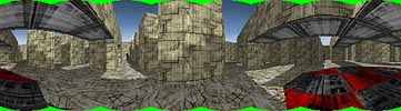
To get rid of these undefined areas, one can crop the image to the largest height that has no undefined parts, or fill these areas with parts of the visible image. I always do the latter, because it is easy to do and it maximizes the vertical pan.
This is roughly how the projection program which is available on the “practical” page, works. Actually there are a lot of refinements which make the program more efficient, but I won't discuss these here.
Of course, after transforming all the pictures, they need to be merged into a single file, which becomes the full cylindrical projection of the scene. This process is often called “stitching” and there are lots of commercial programs available which do the transforming + stitching together.
What happens in a QTVR viewer?
It's quite logical that the transformation used in a QTVR player is exactly the opposite of the transformation described above. We now have a cylinder with our image on it, and we want to project it onto a plane. The calculations are similar to the ones above, so I won't do them here. The coordinates of each point (1, y, z) on the plane correspond with (1, atan y, z/sqrt(1+y2)) on the cylinder.
The panning (looking left and right) is achieved by rotating the cylinder and re-projecting each time. There is something extra, though, about vertical panning.
If you look up and down, the image doesn't just scroll up and down, like in the first generations of 3D action games. Logical, because this is unrealistic. To make things more realistic, a perspective projection is applied (unless you turned it off, of course). This is not discussed here.
I hope this page provided some useful information. If something isn't clear, or you think there is an error somewhere, please mail me.