Converting a USB Power Bank with a Fake Solar Panel into Something Decent
In September 2019 I bought a ‘solar’ USB power bank from an eBay seller. The idea was to have something that I could leave on a windowsill and that would always have enough charge to power USB gadgets, or to carry when traveling to have at least some emergency power handy. I know one should not expect too much from these things because the solar panel is usually woefully undersized compared to the battery capacity, and also only puts out a decent amount of current under direct summer sunlight. However, with the one I received, I could have put it under the desert sun at the equator and it still would not have acquired any additional charge, on the contrary.
Intro
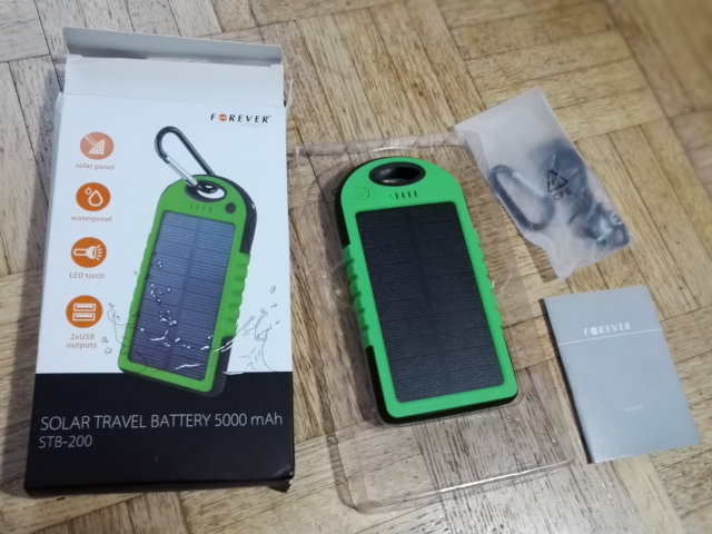
The power bank is of a typical design that seems to have been copied a lot during the past decade. This particular one was branded ‘Forever’ and appears to have been made for the Polish market. The specifications promise 5000 mAh and a 100 mA solar panel. The actual battery capacity is probably closer to 3000 mAh and the actual current rating for the panel should be somewhere around −3 mA… It is also called ‘waterproof’ although in reality it is at best spatter-proof. Water can easily get in through the gap between the panel and the body, the button, or the holes under the rubber bumpers.
The reason why this ‘solar charger’ would never charge in sunlight, was because it was fitted with a fake solar panel. That's right, someone had actually done the effort to produce both fake panels, as well as possibly modifying the typical power bank circuit to maintain the illusion that it was a real panel. I am not 100% sure about the latter, it is also possible that they merely abused existing provisions for a separate sensor.
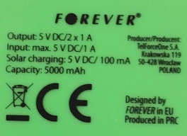 A heap of lies! At least a real CE logo, and no ‘China Export’…
It is quite baffling that so much effort has been spent on faking a solar panel, but this does fit within the typical Chinese practice of cutting every cent off production by removing things that are not immediately obvious to the user. In this case, because the solar panels on power banks like this only work well under specific conditions, it made some sense to also get rid of those specific conditions and manufacture something that never works at all. Still, it is obviously a big and inexcusable scam to sell this as a “solar” device. Yes, you can still charge this bank using the cable, but that is not the point. It is not what it is claimed to be on the package.
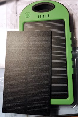
The eBay seller refunded the whole transaction immediately upon receiving my complaint, and he was going to have a word with his provider upstream. I have no doubt that he was genuinely unaware of the deception. When taking one of these things out of its packaging and holding it under a light source, an LED will actually light up and react to the amount of light. Even a seller who does the effort of checking that what they are selling matches the product description, will be easily fooled. I did have a bad feeling about the panel the first time I looked at it because it does look unusual: the lines that are supposed to be the conductors of the solar cells, were too regular and too white. But then I also got fooled—at least for a few hours—by the green LED reacting to incoming light. I assumed the cells had been manufactured with some newfangled process that resulted in the suspiciously regular white lines…
Anatomy of a Scam
The fake panel is based on the same kind of substrate as a real panel, and has the same kind of rough transparent top surface. Instead of real cells however, in between the substrate and top layer is a sheet of plastic with a pattern printed on it that almost looks like solar cells. The real pièce de résistance however, is a well-hidden photoresistor in the middle of the panel. This allows an LED to respond to incoming light. The rough top layer makes it difficult to see this sensor, only with the right incidence of light it becomes visible.
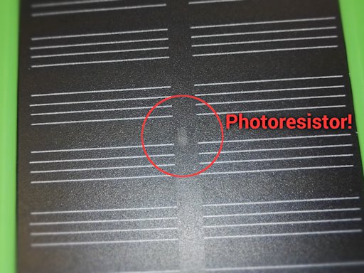
If you suspect you may also have bought a scammy device like this, there is an easy way to see whether it is a real panel or not. Put it under enough light that the indicator LED will light up. Then go with just your fingertip across the centre region of the panel. If the LED suddenly dims to total darkness when touching only a specific spot, you have just found the photoresistor that is being used to make the fake panel seem real. If instead you have to cover at least half of the whole panel to dim the LED, you can be pretty certain it is real.
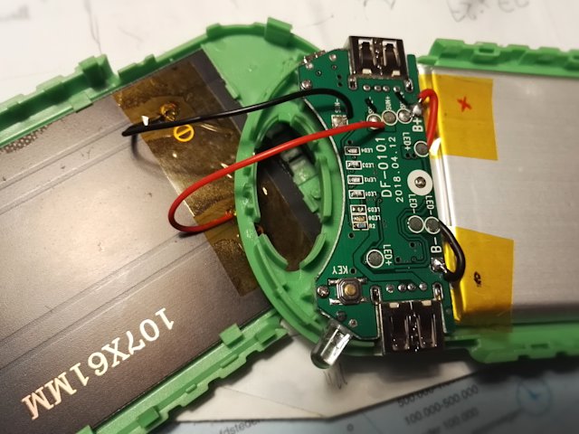
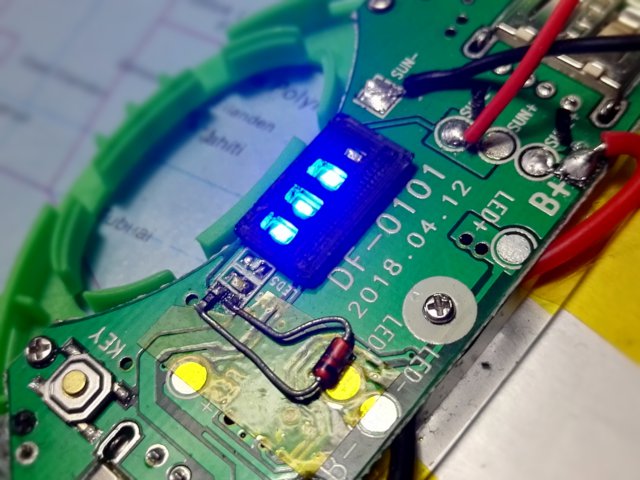
When taking the device apart, which is quite easy because it is a snap-together design without screws, we can see how the trickery was implemented. There are two pairs of contacts labeled ‘SUN’. The regular ‘SUN’ ones are actually meant for a real solar panel. The ‘SUN2’ contacts however, are meant for a photoresistor. They put the indicator LED plus a series resistor in a straight path between the battery contacts, with the photoresistor closing the circuit. The more light impinges on the photoresistor, the more current it conducts and the brighter the LED lights up. Dead simple and effective. Again, I cannot tell whether they specifically modified the PCB design to add these contacts and enable selling both real and scammy solar power banks with only one PCB production line, or the SUN2 contacts are also used on real banks…
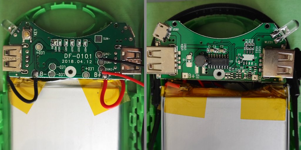
Next to the fake panel and the exaggerated battery capacity, there is also a slightly subtler kind of deceit going on. The HT4936S IC that controls the power bank, only has 4 outputs for indicator LEDs. As you can see in the photos however, this bank has 5 blue LEDs (the sixth LED is the green solar indicator, but it is not connected to the IC). The first versions of this style of power bank did have only 4 LEDs. But in China, more is always better, therefore they duplicated the lowest charge level LED by putting two in parallel. The IC can handle this extra load, although when looking carefully, one can see that the two LEDs in parallel do have a lower intensity each because the single output pin starts to lose voltage due to the higher current. This trick of adding a dummy LED gives a false impression that the battery has more juice in it than it actually has. The 4-LED indicator would show 2 out of 4 LEDs at 50% level, which is fair. The fake 5-LED indicator on the other hand would show 3 out of 5 LEDs, making it seem you still have 60% juice left. At 25%, you would believe you still have 2/5 = 40% left. The USB sockets would then shut down way sooner than expected.
Mounting a Real Solar Panel
Aside from the scammy aspect, this is actually a pretty decent power bank. The outputs can only reliably deliver up to 1A of current but despite this, for some reason they are able to charge my Honor 7 smartphone much quicker than other USB chargers or even a USB port on a PC. The flashlight is also handy and despite the lack of true waterproofness, the design of the case is pretty nice. Even though the battery does not have its promised 5000 mAh capacity, it is still adequate. Therefore I started wondering whether I couldn't achieve my original goal of true solar charging. After all, I had not much to lose because with my eBay costs refunded, I got this thing for free.
 The real panel on top of the fake one.
The only things that were missing, were an actual real solar panel, and a Schottky diode at the location marked ‘D1’ on the PCB. This diode is essential to prevent the battery from discharging across the solar panel when no light is shining onto it. I still had a pile of MBRS130LT3 diodes which are a pretty good fit. All I then needed was an actual solar panel. The panel size is 107×61 mm. I looked in various shops and the most common panel in this size is a polycrystalline piece of junk with huge gaps between the cells. Luckily I found one eBay seller (gadgetskingdom) who seemed to offer something better: a panel well-covered with mono-crystalline cells. Of course one can never be sure with these Chinese sellers, but what I received did match the photos and it is actually a high-quality panel. It is made so cleanly that I almost feared they had again sent me a piece of plastic, but it did easily produce 60 mA under a late-autumn sun behind double glass, so I am sure this will reach the promised 160 mA or even more under a direct summer sun.
I mounted the real panel and connected it to the ‘SUN’ contacts (the SUN+ and SUN2- are actually the same, so I reused that one out of sheer laziness to avoid having to add solder to the other pad). I did not have to do anything else, the solar indicator LED is connected such that it works both for the fake and real panel configuration without modifications (although it is recommended to make a small modification after all, see below).
Other Tweaks
While I was hacking this thing anyway, I removed the deceitful fifth duplicated charge indicator LED. This also yields a tiny reduction in wasted current draw while the power bank is active, because the LEDs stay lit as long as a device is drawing current from the battery.
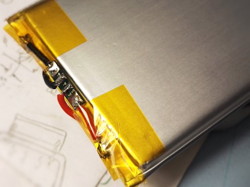
Another important change to make, was to add a protection circuit to the battery. Normally the HT4936S will prevent the LiPo from overcharging, but the solar cell is connected almost directly, with the IC not being in the loop and unable to cut off the current. (The IC also protects against over-discharging, although I have the impression that it does not cut off the current drawn by the flashlight LED, another reason why a protection circuit is a good idea.) The risk that the panel can push the LiPo far above 4.2 V is small (especially where I live), but it exists. Therefore I desoldered the battery and reconnected it through a tiny LiPo protection PCB of which I had bought a whole bunch through AliExpress years ago. This PCB may look under-dimensioned for a cell this size, but because there should never be currents much larger than 1 A, it is actually perfectly adequate, and it fits nicely in the confined space.
Obviously if you plan on doing this kind of hack, BE VERY CAREFUL. I do not know what kind of short circuit current a LiPo cell this size can draw, but I can tell it is a whole lot. I tested a puny 120 mAh cell lately and even that one could achieve 6 A. Compared to that, the cell in this pack is pretty much a small bomb.
I then applied some finishing touches: I 3D printed a tiny plastic piece to prevent the light of the blue LEDs from leaking into each other, this makes it much easier to distinguish between the charge levels.
I was also annoyed by the fact that the green solar indicator LED lit up already when the slightest amount of light impinged on the solar panel. To fix this, I added a 2.4 V zener diode in series with the LED. This makes the LED only light up when there is a voltage across the panel that is at least theoretically able to charge the battery. Better would be to make this LED only light up when actual current is flowing into the battery, but there's no room to add such a circuit. This zener also helps to avoid that the green led will go up in a puff of magic smoke when very strong sunlight would cause a very high voltage across the panel.
Conclusion
Now I do have a decent and true solar power bank, probably with one of the better solar panels available in this size. It will still inevitably charge slowly, because even when the panel delivers its maximum of 160 mA, it still takes 19 hours to fill an idealised 3000 mAh battery, more in reality. But at least it will actually charge. And it has only cost me the price of a solar cell (and some time).
It is noteworthy that the HT4936S chip and similar power bank chips, have the annoying property of only delivering continuous 5 V output when sufficient current is being drawn from the outputs. When the current drops below a certain level, the IC will drop the output voltage to zero for a second every 10 seconds. I think the idea behind this, might be to make cell phones repeatedly play their ‘charging’ tune to signify that the phone is as good as fully charged. This works by the grace of most phones reducing their charge current when the battery is almost full. The downside is that this makes it annoying to use power banks like these for powering USB gadgets like lamps, because if the gadget doesn't draw enough current, it will briefly stop working every 10 seconds. The only workaround is to connect a second USB device to increase current draw.
If you have any comments about this article, you can post them on the accompanying blog page.