Bicycle Dynamo LED Driver
This page describes how I converted my bicycle's lighting to LEDs in a time when incandescent bulbs were still the norm. I went through a few iterations and the last one is still in use on my main commuter bike.
I have been fascinated by LEDs since they started becoming more efficient than the usual red indicator LED in old electronic devices. With the advent of white LEDs, the possibility arose of actually using them as practical replacements for other light sources. A white LED is in fact a blue LED with a phosphorous layer on top that converts the blue light into a wider spectrum. Depending on the composition of the phosphor layer, the typical ‘cold white’ or a ‘warm white’ colour can be obtained, the latter more resembling the colour of incandescent bulbs.
LEDs have two big advantages over a lot of other bulbs. First, they last much longer when treated properly. Second, especially the latest high-efficiency types are much more efficient than many other light sources. The ancient incandescent bulb in the very best cases still only outputs about 5% of its power as visible light, while an LED can easily reach 20% or more. Especially when a single colour is required (e.g. red), an LED will beat almost every other light source because it emits light of the desired colour right away. For an incandescent bulb, a filter would need to be placed in front of the light, further reducing the overall efficiency.
First Prototypes
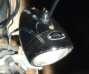
I tried to get hold of newer and more efficient LEDs whenever I could (at one time around the year 2000 I had to pay an outrageous fee for the shipping of what I thought were ‘free samples’). Eventually I figured out that LEDs were ideal replacements for the ever failing incandescent bulbs in bicycle lighting. Therefore my goal was to upgrade the bulbs in my ‘retro’ chrome-plated bike light with solid-state electronics.
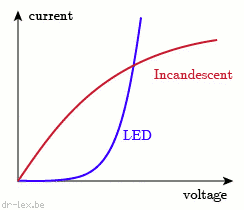
The main problem with LEDs and a disadvantage over incandescents is that LEDs are much more sensitive to the voltage that is used to drive them. Incandescents have a voltage/current curve that gets increasingly flat at higher currents (see graph). They are self-stabilizing: the hotter they get, the less extra current they tend to draw for an equal increase in voltage. For an LED it is the other way round. Its curve looks like an exponential curve, which means that in its operational region, small increases in voltage will produce ever larger increases in current. To make things worse, as an LED heats up it will start drawing even more current. If one would just hook up an LED to a battery, it will likely burn out unless the battery happens to be unable to deliver more than the maximum current for the LED (which is a trick often used for small LED flashlights powered by weak button cells).
Today one can buy clip-on LED lights for bicycles everywhere and they are dirt cheap. But back then you would pay three times as much just for a single bare LED and then you'd need to figure out a way to drive it. I wanted my bicycle light to have the following properties:
- Work without requiring any maintenance. That means no batteries. I consider batteries that need to be explicitly replaced or manually charged a nuisance that should be avoided whenever possible. Therefore requirement #2:
- Run from a dynamo. A good hub dynamo is a reliable power source and causes no noticeable drag. I installed a Shimano DH-DN30, which still works perfectly after 15 years.
- Keep working for a while when I come to a halt. The disadvantage of a dynamo is of course that it stops producing power when the wheel doesn't turn, but there are ways to store electricity. Obviously, a rechargeable battery would be one solution, but there are alternatives that work faster and do not require a charging circuit.
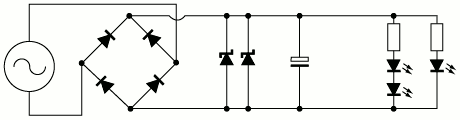
My first prototypes used a rather primitive circuit to power a bunch of white LEDs in series (and a single red LED for the rear light). First a full bridge rectifier converted the alternating current from the dynamo to direct current, then two big fat Zener diodes avoided that the voltage could go above a certain maximum above which the LEDs would go up in a puff of toxic smoke. A big fat capacitor served as the accumulator. This kind of circuit worked, but had two major problems: first, it is inefficient as hell. To get decent light output even at low driving speeds, the Zener voltage, i.e. the voltage at which the LEDs would produce the most light, could not be too high. This in turn meant that when riding fast, most of the excess current produced by the dynamo would be converted to useless heat in the Zeners. This defeated the whole idea of profiting from the efficiency of the LEDs. Second, to have light output for any appreciable time after stopping the bike, the capacitor needed to be huge. Any normal capacitor was useless, even 10000µF was not enough. To get decent autonomy, I eventually used 5.5V “Gold Caps”, which are normally used as back-up sources for volatile memory. These had a theoretical capacity of one Farad, but in practice they had such a large series resistance that a lot of that capacity got wasted. But with two in parallel, the light did keep working for a few dozen seconds, of course with a gradual decay.
A third problem was that despite the fact I used heavy duty Zener diodes, even two in parallel, they would consistently die after a while. This was probably because they had to burn off too much excess current while driving at high speeds. The whole idea of putting Zeners in parallel is flaky anyway: any slight difference in the Zener voltage will cause one of the diodes to draw most of the current and wear out first, hence the second diode was only useful as a back-up. And that was only the case if the first diode failed as an open circuit and not a short — which is of course the favourite way for Zeners to kick the bucket.
2006: 1W Upgrade with Supercapacitors
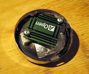
After a while, LEDs became available in other formats than the classic 5mm bulb and with higher power ratings. Luxeon started producing 1W LEDs in various formats, one of which was the “Luxeon Star/O”, which included a collimator lens to bundle the output into a nice beam about 12° wide. This was an excellent candidate for a high-power bike light. However, to drive this kind of LED about 350mA is required, which makes the primitive circuit descibed above completely unusable. The year 2006 was nearing its end and I got tired of the shortcomings of my prototype lights, so it was time for a redesign.
The best way to drive an LED is to use a current source, which avoids the problem of the finicky exponential V/I curve. A current source adapts the voltage such that the current going through its load (the LEDs) is constant, which is exactly what we want because the light output is (roughly) proportional to the current. The cheapest and simplest approximation of a current source is to put a resistor in series with the LED and apply a voltage. When the voltage rises, the voltage drop over the resistor increases as well and the increase in current is limited. As can be seen in the scheme above, the first prototypes of my semiconductor bike light used this method (together with the Zeners to limit the maximum voltage). Of course, the range in which the resistor can regulate the current is pretty limited, and the voltage drop over the resistor incurs a loss of efficiency.
A proper current source would also eliminate the gradually decaying light output as the discharging capacitor (or whatever energy storage device used) delivers an ever decreasing voltage. However, for a capacitor this means its voltage would drop linearly as it gets ‘sucked dry’ to maintain a constant current through the LEDs. This would mean I would need an insane amount of storage to keep the 1W Luxeon working at full brightness for any appreciable time. The main priority was to keep the rear light running as long as possible (which is also required by regulations for new bikes). The rear light is a low-power efficient red LED. I didn't care if the front light would dim much faster. Therefore I opted to power only the rear light through a current source and let the front light get whatever voltage was available on the storage device. Together with a ‘poor man's current source’ in the form of a small series resistor, the front light should keep producing a reasonable brightness during a reasonable time.
Speaking about storage, even without a current source the old Gold Caps were completely unsuitable to power the 1W Luxeon, because due to their high series resistance they couldn't deliver any current remotely near to 350mA. The only real options were to use either rechargeable batteries, or even more powerful capacitors. Rechargeable batteries would need yet another extra circuit to properly charge them, therefore my preference still went to capacitors. Those proved to exist in the form of ‘supercapacitors’ or ‘ultracapacitors,’ that had started to become affordable and available to the general public at that time. These are a kind of intermediate between a battery and a capacitor. They were pretty expensive as well, but since I was already shelving enough money on state-of-the-art LEDs, I didn't really care. I was determined to have a full solid state bike light while everyone else was still pedaling electrons through their tungsten wires.
Switching Power Supply
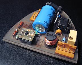
Bringing everything together, the strategy was as follows. As a first stage I would again use a bridge rectifier followed by a Zener and capacitor. The difference is that I would now use my own full bridge rectifier built from the highest efficiency Shottky diodes I could find to reduce the voltage drop from the ±1V that many prebuilt rectifiers often have, to about 0.3V. Next, the troublesome parallel Zeners now became two 5.6V Zeners in series to get a total Zener voltage of 11.2V. Plus, now the two diodes properly share the load, which will be much smaller anyway because the dynamo will not easily reach 11.2V. Finally, the ridiculously large capacitor became a reasonably sized electrolytic capacitor. The only function of this first stage is to provide a rough unstable DC voltage for the following stages.
The second stage is a switching regulator (MC33063) that aims to output a voltage of about 3.5V. This is slightly more than the Luxeon needs at full power to cater for its small series resistor. After this regulator comes the ultracapacitor and the 1W Luxeon LED (+ series resistor). Mind the difference with the old circuit: it will be much easier to obtain those 3.5V even at low driving speeds, given that a dynamo is designed to produce a nominal AC voltage of 6V under load. At high speeds, the switching regulator will simply cut off the excess current instead of turning it into heat. This solves both the inefficiency and the low output at low speeds.
Finally, a third stage is another switching regulator (TPS61040) that is configured as a current source for the rear light. Because the contact with the rear light might be interrupted, a set of Zeners is placed on the PCB to avoid that the current source blows itself up while trying to push a current through an open circuit. I won't go into the details of configuring the switching regulators, their datasheets contain good information about this. Generally they need to be optimised for a fixed input and output voltage but in this case the input voltage can vary wildly, so I had to configure them for some average value.
In summary, the first switching regulator tries to keep the ultracapacitor charged at the same voltage that the 1W LED needs at full brightness. This LED will gradually fade out while the ultracapacitor discharges. However, the current source for the rear light will cause it to keep working at full brightness as long as there is enough voltage left on the discharging ultracapacitor. This proves to be in the order of a few minutes, a big step up from the few dozen seconds of the old circuit.
Balancing the Ultracapacitors
One problem with ultracapacitors is that the high-capacity, high-efficiency ones have a maximum voltage of 2.3V, some even lower. Because I need 3.5V, I need to put two in series. This causes a risk of unbalance if the capacitors are not well matched, which means that one of them could charge up to more than 2.3V and become damaged. In my case this would probably never happen, but I built the entire circuit such that I could reconfigure it to work up to the full 4.6V in the case I would ever want to replace the LED with something exotic that needs such a voltage. And, I simply wouldn't want to take any chances because the ultracaps were pretty expensive. There are multiple ways to ‘balance’ ultracapacitors in series. The simplest method is putting a resistor in parallel with each capacitor. If one capacitor is charged more than the other, its resistor will draw more current and balance it out. However, this is a primitive method that will not avoid excessive unbalance and it will slowly drain the capacitors when not in use. More advanced methods use active circuits that only drain the capacitor when necessary.
In my case an active circuit would probably be overkill though, and take yet more space in the already cramped confines of the headlight. But I didn't like the prospect of resistors constantly draining the power. Therefore I tried something more clever. I needed something that would draw nearly no current below ±2.2V and then quickly ramp up. A Zener would be ideal, but there are no Zeners at such low voltages. However, there are LEDs with a forward voltage around 2.3V. That's right, I'm balancing the ultracapacitors that power my other LEDs with more LEDs! I used ‘SuperFlux’ LEDs because they allow a higher current than the typical 20mA of regular LEDs. The LEDs that start to draw considerable current around 2.2V proved to have a nice amber colour that will however never be visible unless the bike light is disassembled while fully charged. It is a nice indicator though of any unbalance in the capacitors. Eventually the LEDs always prove to light up equally, therefore I seem to have gotten two well matched ultracapacitors.
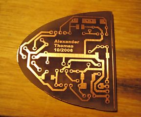
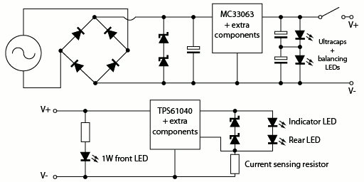
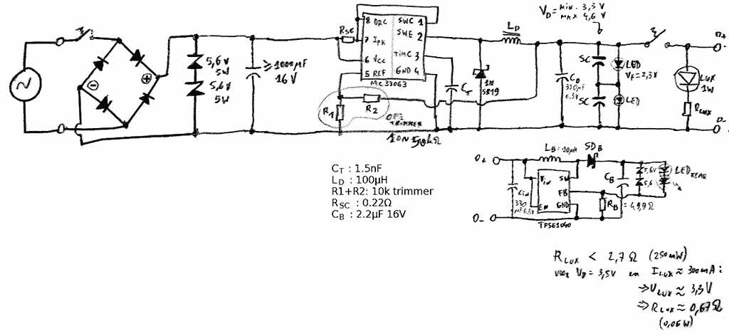
If you want to have a more detailed version of the complete circuit with the values of the most important components indicated, the image below links to my original back-of-the-envelope schema that I eventually implemented. Some component values like the inductances and timer capacitors can probably still be tweaked for better efficiency, but this is the circuit that has been serving me without problems since 2006.
Conclusion
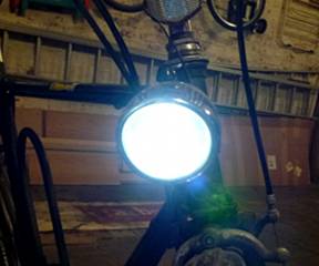
The light works very well, the 1W LED is bright enough to light the road at night and avoid the many potholes in the asphalt of the horrible Belgian roads. I notice no difference in required effort between the light on or entirely turned off (aside from a switch to disconnect the ultracapacitors, there is also a global switch to disconnect the dynamo), although when letting the wheel spin freely it does stop much quicker with the light turned on. So I didn't acidentally build a perpetuum mobile, dang.
I built this last iteration of my solid-state bike light at the end of 2006 and it still works at the time of this writing (2014). Aside from a few glitches there have been no failures. The switching IC of the rear light current source has failed on one occasion, I suspect because the long wires had acted like an antenna catching severe EMI while my bike was parked outside during a thunderstorm. In an attempt to avoid this I replaced the wires with twisted pairs, and there have been no failures ever since.
I could probably easily swap the now obsolete Luxeon Star/O with a new LED that is even more efficient, but it works well enough as it is. I would like to see this thing fail from usage, but I think It will probably survive me. (Cfr. below: I eventually replaced it anyway.)
Now that LiPo batteries have become much cheaper and easily obtainable with an overcharge and deep discharge protection circuit, it would be a good option to replace the ultracapacitors with a small LiPo cell, especially given that it works at a similar voltage as required for the circuit. I do have some doubts however how well it would work in freezing weather (which is no problem at all for the capacitors). Because I am happy enough with the capacitors I do not intend to swap them for a battery, but if you're going to design your own circuit it is certainly an option worth considering. A battery would give far longer autonomy than ultracapacitors of the same physical size. If LiPo or Li-ion does not fit your needs, plain old NiMH may be a good alternative.
2016 Update: Cree LED Upgrade
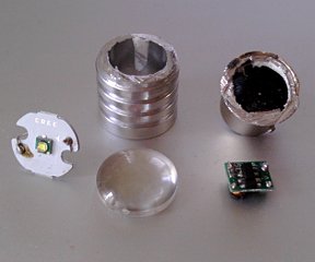
After more than nine years of service, the light is still going strong. However, it seems the Luxeon has lost a lot of its intensity. Either that, or it just seems less bright due to the LED lights on retail bikes having become brighter. I also noticed that the narrow beam of the Luxeon incurred a risk that motorists often failed to notice me when I was not heading directly towards them, especially in rainy weather. So, it was time for an upgrade.
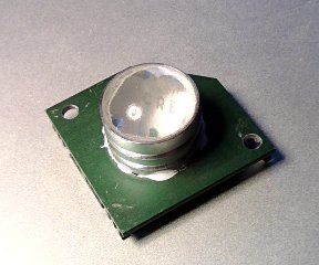
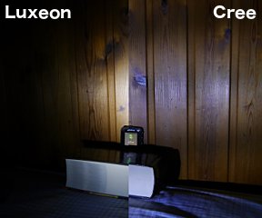
It is surprisingly difficult nowadays to find the same ready-to-use kind of assembly with a lens as the Luxeon Star/O. I solved this problem by buying one of those cheap Chinese replacement car brake lights based on a Cree LED, which comes with its own lens that produces quite a wide uniformly lit beam. I took it apart and mounted it on the same heatsink as the Luxeon. Basically, it is a drop-in replacement and uses exactly the same power. However, as you can see from the photos below, it is a huge improvement.