Silly Hacks
Here's a collection of some small hacks that were often performed more for the fun of it than for real practical use, although each hack still has the potential to be useful in some way. For instance, I have used the hacked ADB II mouse on a regular basis.
- Apple ADB II to optical USB mouse (2007)
- Overclocking a G3 iBook (2003)
- The miniature ‘GRUB’ keyboard (2008)
- XBox 360 candy buttons backlight (2011)
- Single op-amp asymmetric oscillator (2014/01)
- White LED in 4th generation IXO (2018/04)
- ‘Kinzyobi,’ another piece of e-waste avoided (2021/05)
- Perfecting a pencil sharpener (2023/12)
Apple ADB II to optical USB mouse (2007)
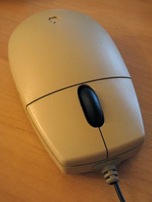
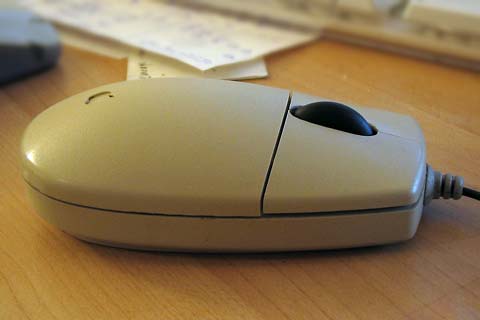
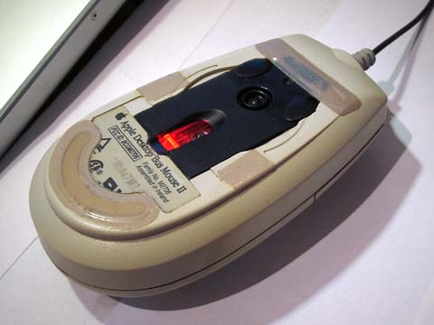
People who have used a Mac in the mid to late nineties, should be familiar with the Apple ADB II mouse. It became kind of a prototype for the ideal computer mouse shape and could be spotted in the majority of computer-related adverts from the late nineties and beyond, even those that had nothing to do with Macs. This was probably not only due to its pleasing aesthetics but also its instantly recognisable shape. The only (debatable) flaw that could be attributed to this mouse is its single button, a principle that Apple only (partially) gave up when introducing the Mighty Mouse in 2005.
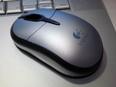
We had a bunch of these mice lying around at home, most of them jobless since the transition to USB Macs. I also had a Logitech USB Notebook mouse which I used with my MacBook Pro, but I didn't like its shape. Inspired by the nice ADB I to USB hack by command-tab, I decided to have a go at fusing the classic ergonomics of the ADB II mouse with the modern internals of the Logitech. If successful, I would have — as far as I know — the first ADB II mouse with two buttons and a scroll wheel, the dream of many a Mac user in the nineties.
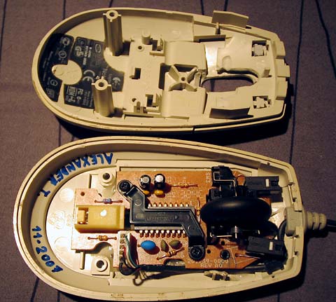
As you can see from the photos below, it worked out and the mouse works perfectly. With the help of a dremel tool, a fretsaw and some epoxy glue, the internals of the Logitech fit nicely inside the ADB casing. By sawing the single button in two halves with a hole in between, the transformation was complete. The only problem were the switches: I had to move them forward on the PCB to make the protrusions in the sawn-in-two button line up. This involved interrupting traces and drilling new holes in the PCB. Finding the right distance between the buttons and the switches was a matter of trial-and-error.
I didn't go as far as looking for a matching USB cable. The scroll wheel is black anyway so the black cable is acceptable. For the finishing touch, I restored as much of the original ADB II sticker as I could, and used some teflon tape to replace the worn-out original teflon pads.
Overclocking a G3 iBook (2003)
Many hardcore PC enthusiasts scoff at Apple Macintosh computers because there's little to nothing to tweak about them. Those people like to try twenty different thermal compounds to get a few degrees lower temperature on their CPU, and push it just a few extra MHz faster just for the heck of it. Increasing the speed of your CPU is called ‘overclocking’ and contrary to popular belief, it is actually possible to overclock even some of the most consumer-oriented Macintosh computers, at least in the old days. This is also something I tried just for kicks, because in practice the speed gains attainable through overclocking are always below the threshold where a human can notice any appreciable difference — except if you're going for the really fancy and really unpractical stuff like liquid nitrogen cooling.
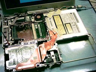
I had stumbled upon a few articles on MacBidouille and xlr8yourmac that explained how the model of G3 iBook I had back then could be overclocked. It involved actual soldering on the motherboard, and required taking apart the entire iBook down to almost the last screw. Anyone who has worked on these monsters will testify that taking them apart is pure hell. But I had to do it anyway because I wanted to swap in a bigger hard disk, so I decided to give the overclock a try as well. It only required removing a few extra of the screws, for a total of about 37. Mind that there are seven or eight different types of screws in this thing, as well as lots of aluminium and plastic tape holding everything together. This is not an example of Apple's finest engineering.
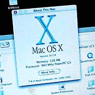
Doing the overclock involved removing an actual physical resistor on the motherboard near the CPU. This was not trivial because they were of about the smallest SMD components that exist. I still cannot fathom how I did it back then without my hot air soldering gun but I managed to remove the resistor required to boost the machine from its original 800MHz to 900MHz. The overclock actually worked and the machine even seemed to run stable. However, after some serious stress testing it started to act really weird, like spontaneously typing garbage in terminals and programs randomly crashing. I want my machines to be perfectly stable in all circumstances, so my only option was to go through all the 37 screws again and re-solder the resistor on the motherboard. So, it was an utterly pointless but fun experiment, and a lot more hardcore than just changing a setting in the BIOS. Eat your heart out, PC overclockers.
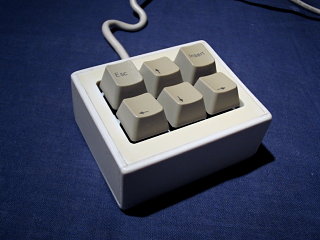
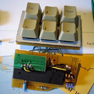
The miniature ‘GRUB’ keyboard (2008)
This was more an exercise in making something useful from scrap material, although there was an actual reason for making it. At a certain time I ran two computers with the same keyboard and mouse. Sometimes I had to reboot one of the PCs while working (or gaming) on the other one and it was cumbersome to switch the keyboard just to get into the GRUB boot menu and choose the correct entry. I did have an USB switcher, but it sometimes made the computers or peripherals connected to it go crazy.
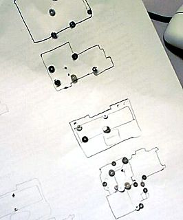
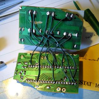
Therefore I butchered an old Cherry PS/2 keyboard and converted it to a miniature keyboard with only six keys that were sufficient for browsing through the GRUB menu and even through some simple webpages. The casing of the mini-keyboard was completely made from cut-up parts of the original keyboard.
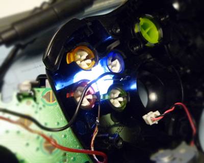
XBox 360 candy buttons backlight (2011)
I bought a USB XBox 360 controller to play racing games on my computer (a keyboard is horrible to get accurate steering and throttle). I was disappointed that the ABXY buttons were not illuminated, therefore I did the pretty popular hack of making them light up when the controller is plugged in. Most people do the effort of placing a separate LED inside each of the buttons, but I figured that by drilling some holes in strategic places and using transparent silicone kit, I could distribute the light of a single efficient white LED across the four buttons. This works indeed and it gives the buttons a more unique glow that changes when they are pressed.

Single op-amp asymmetric oscillator (2014/01)
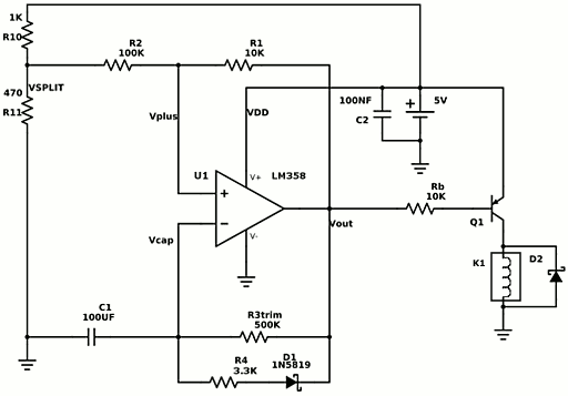
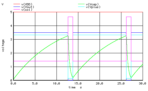
This was a tiny cancelled project that was intended to remedy a problem with a dodgy heating installation, where I suspected that a valve got jammed if the circulation pump ran continuously for too long. As replacing the valve was very cumbersome, an experimental fix was to add a circuit that power cycled the pump every ten seconds. The circuit runs on 5V and uses a single op-amp, a diode, a capacitor, a transistor, and a bunch of resistors to give a short pulse to a relay every dozen seconds. The period between pulses can be adjusted with a trimmer. The circuit is a basic Schmitt oscillator with a diode allowing the capacitor to discharge much faster than to charge, or in other words, providing a duty cycle much smaller than the usual 50% of a Schmitt oscillator.
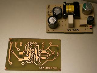
I got as far as creating the PCB with the toner transfer method, when I realised that the problem was due to something else and this hack would barely help to remedy it, so I did not solder it. If you have any use for this circuit, you can download a ready-to-use printable 600dpi image of the PCB, and a SPICE model to experiment with different diodes and resistor values. Although the resistor divider R10/R11 provides a sufficiently stable reference voltage, in the final implementation I buffer it with the second op-amp on the LM358 which comes for free anyway.

White LED in 4th generation IXO (2018/04)
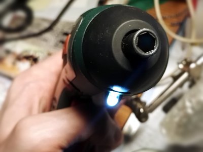
I replaced the rather useless orange LED in a Bosch IXO screwdriver with a much better white one, which wasn't trivial due to voltage requirements. Details can be found in the blog post.
‘Kinzyobi,’ another piece of e-waste avoided (2021/05)
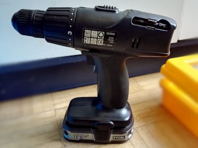
I have a rather ancient cordless drill/screwdriver of the obsure brand Kinzo that originally had a NiCd battery pack. This pack self-discharged quite quickly and took ages to charge, hence I didn't often use this drill which made the batteries degrade even quicker. Eventually the battery became unusable. Technically it was possible to have the pack refurbished with new cells, but the cost would be preposterous for this kind of budget brand tool. Moreover, I would again have a clunky NiCd or NiMH pack that would steadily rot away like the previous one.
I had already put some effort into repairing this drill by replacing the switch a while ago, so I was reluctant to just toss it like most would do at this point. And most of all, I am a tinkerer. What if I could retrofit a Li-Ion battery? I found out that Ryobi One+ batteries have an interface not too dissimilar from the one on this tool. Voltage is 18 V instead of 14.4 V, but a YouTube video confirmed that 14.4 V tools will usually work fine on the higher voltage. I had nothing to lose if it would go up in smoke anyhow: I could simply buy a Ryobi drill.
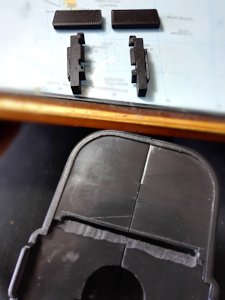
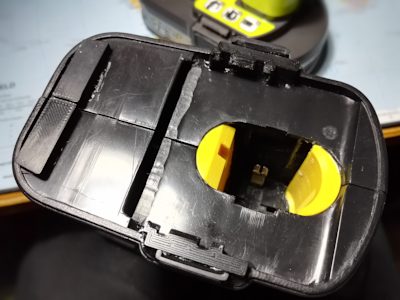
It only took some minor hacking in the tool body to make the battery fit perfectly. 3D printed parts allow the battery to snap in place like on a real Ryobi. The result works perfectly. Because this battery is much more reliable and charges very quickly, I'll probably be using this drill more often now. What I particularly like about Ryobi is that they use the same battery form factor for many of their tools, so I'll probably be buying some actual Ryobi tools as well…
Perfecting a pencil sharpener (2023/12)
Another hack mostly performed just to prove a point, and also to relax by for a whole day focusing onto something silly that does produce at least a marginal benefit—try it, it is a great stress relief.
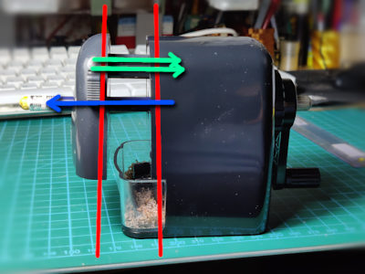
Automatic pencil sharpeners are handy, but many have the same non-ideal design where the springs that pull the pencil into the sharpening mill, are positioned at one side away from the pencil. This produces a torsional force, and unless the carriage holding the pencil is mounted on rails with tight tolerances, the whole thing will be pulled askew and the pencil does not enter the mill perpendicularly. The result is that the sharpened tip ends up being skewed as well. I have a Möbius+Ruppert sharpener that exhibits this problem.
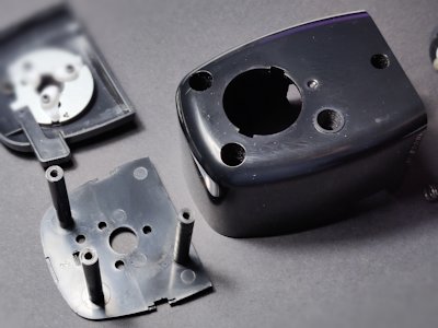
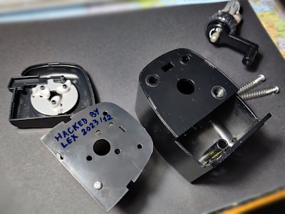
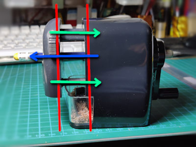
The remedy again relies on the magic of 3D printing, and some carefully drilled holes. The solution is to relocate one of the springs such that the pencil is perfectly in the middle, eliminating the torsional force. By printing the parts in the same ABS plastique as the sharpener, I could solvent-weld them in place and end up with a very clean end result.
I don't really get why the sharpener was not manufactured this way, because there is ample room for relocating the spring. Either someone favoured looks over function, or it was cheaper to make injection moulds for the suboptimal design…
There is sill some asymmetry, because they cheaped out on the sharpening mill by only using one cutting roller. The better sharpeners have 2 cutters. However, this does not matter much because symmetry is approximated by means of the whole assembly rotating around the static pencil.
Another problem with this particular sharpener is that the rubber bands grabbing the pencil tend to harden over time, losing their grippiness. A solution is to soften the bands again by soaking them in WD-40 for several hours, but this has to be repeated about twice a year. Other solutions are to replace the bands with small O-rings, or attach a strip of rubber to the edge of the grabbers in any other way. (I also tried making bands from silicone caulk in 3D printed moulds, but the caulk proved to be too slippery.)